BIOS Setup
3-19
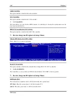
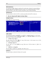
EXT-P2P’s Discard Time:
This item allows you to set EXT-P2P’s discard time.
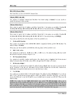
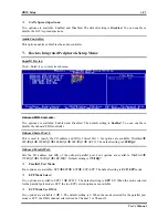
Onboard FDD Controller:
Two options are available: Enabled and Disabled. The default setting is
Enabled
. You can enable or
disable the onboard FDD controller.
Onboard Serial Port 1:
This is used to specify the I/O address and IRQ of Serial Port 1. Six options are available: Disabled
3F8/IRQ4
2F8/IRQ3
3E8/IRQ4
2E8/IRQ3
AUTO. The default setting is
3F8/IRQ4
.
Onboard Serial Port 2:
This is used to specify the I/O address and IRQ of Serial Port 2. Six options are available: Disabled
3F8/IRQ4
2F8/IRQ3
3E8/IRQ4
2E8/IRQ3
AUTO. The default setting is
2F8/IRQ3
.
If you choose
Disabled
, the following items will not be available to set.
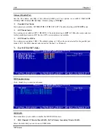
Onboard IR Function:
Three options are available: IrDA (HPSIR)
ASKIR (Amplitude Shift Keyed IR)
Disabled. The
default setting is
Disabled
.
When you select the item IrDA or ASKIR, the following items will be available to set.
RxD , TxD Active:
Four options are available: Hi, Hi
Hi, Lo
Lo, Hi
Lo, Lo. The default setting is
Hi, Lo
. Set IR
transmission/reception polarity as High or Low.
IR Transmission Delay:
Two options are available: Enabled and Disabled. The default setting is
Enabled
. Set IR transmission
delays 4 character-time (40 bit-time) when SIR is changed from RX mode to TX mode.
IR Function Duplex:
Two options are available: Full and Half. The default setting is
Half
. Select the value required by the IR
device connected to the IR port. Full-duplex mode permits simultaneous two-direction transmission.
Half-duplex mode permits transmission in only one direction at a time.
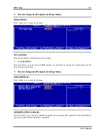
Use IR Pins:
Two options are available: RxD2, TxD2 and IR-Header. The default setting is
IR-Header
. If you choose
RxD2, TxD2
,
your motherboard must support a COM port IR KIT connection. Otherwise, you can only
choose the
IR-Header
to use the IR header on your motherboard to connect your IR KIT. Please use the
default setting.
NOTE:
The setting for item “
RxD, TxD Active
”, also called “
TX, RX inverting
”, allows you to
determine the activity of RxD and TxD. We set it to “
Hi, Lo
”. If your motherboard BIOS uses “
No
” and
“
Yes
” to represent this item, you should set it to the same setting as the NF7/NF7-M/NF7-S. This means
that you should set it to “
No, Yes
” in order to match the transfer and receiving speed. If you fail to do so,
you will not get an IR connection between the NF7/NF7-M/NF7-S and the other computer.
User’s Manual
Summary of Contents for NF7
Page 8: ...1 4 Chapter 1 1 2 Layout Diagram NF7 NF7 S NF7 Series ...
Page 9: ...Introduction 1 5 1 3 Layout Diagram NF7 M User s Manual ...
Page 10: ...1 6 Chapter 1 1 4 Layout Diagram NF7 S2 NF7 S2G Ver 0 22 NF7 Series ...
Page 29: ...Hardware Setup 2 19 NF7 S2 NF7 S2G User s Manual ...
Page 68: ...3 34 Chapter 3 3 34 Chapter 3 NF7 Series NF7 Series ...
Page 72: ...Appendix B B 2 NF7 Series ...
Page 74: ...Appendix C C 2 NF7 Series ...
Page 76: ...D 2 Appendix D NF7 Series ...
Page 84: ...F 4 Appendix F NF7 Series ...

