BIOS Setup
3-3
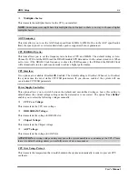
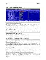
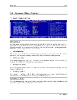
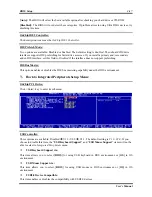
Multiplier Factor:
This item sets the multiplier factor for the CPU you installed.
NOTE:
Some processors might have this multiplier factor locked, so there is no way to choose a higher
multiplier factor.
AGP Frequency:
This item allows you to set the AGP clock speed from 66MHz to 99MHz. Due to the AGP specification
limit, the speed you set over its standard clock speed is supported, but not guaranteed.
CPU FSB/DRAM ratio:
This item allows you to set the frequency ratio between CPU and DRAM. The default setting is
Auto
.
Choose
By SPD
to let the BIOS read the DRAM module SPD data and set to the values stored in it. When
set to
Auto
, if the DRAM Clock frequency is above the FSB frequency, the FSB and the DRAM Clock
will automatically run in synchronous mode to achieve higher performance.
CPU Interface:
Two options are available: Disabled
Enabled. The default setting is
Disabled
. When set to
Disabled
,
the system uses the most stable CPU/FSB parameters. If you choose
enabled
, the system will use
overclocked CPU/FSB parameters.
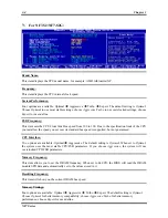
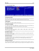
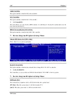
Power Supply Controller:
This option allows you to switch between the default and user-defined voltages. Leave this setting to
default unless the current voltage setting cannot be detected or is not correct. The option “
User Define
”
enables you to select the following voltages manually.
CPU Core Voltage:
This item selects the CPU core voltage.
DDR SDRAM Voltage:
This item selects the voltage for DRAM slot.
Chipset Voltage:
This item selects the Chipset voltage.
AGP Voltage:
This item selects the voltage for AGP slot.
ATTENTION:
A wrong voltage setting may cause the system unstable or even damage the CPU. Please
leave it to default settings unless you are fully aware of its consequences.
CPU Over Temp. Protect:
This item sets the temperature that would shutdown the system automatically in order to prevent CPU
overheats.
User’s Manual
Summary of Contents for NF7
Page 8: ...1 4 Chapter 1 1 2 Layout Diagram NF7 NF7 S NF7 Series ...
Page 9: ...Introduction 1 5 1 3 Layout Diagram NF7 M User s Manual ...
Page 10: ...1 6 Chapter 1 1 4 Layout Diagram NF7 S2 NF7 S2G Ver 0 22 NF7 Series ...
Page 29: ...Hardware Setup 2 19 NF7 S2 NF7 S2G User s Manual ...
Page 68: ...3 34 Chapter 3 3 34 Chapter 3 NF7 Series NF7 Series ...
Page 72: ...Appendix B B 2 NF7 Series ...
Page 74: ...Appendix C C 2 NF7 Series ...
Page 76: ...D 2 Appendix D NF7 Series ...
Page 84: ...F 4 Appendix F NF7 Series ...

