BIOS Setup
3-5
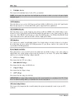
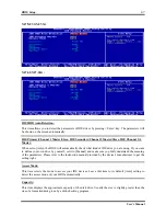
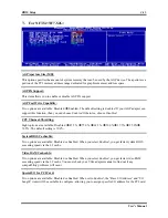
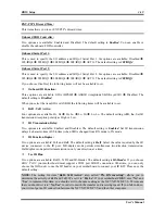
Row-active delay:
Fifteen options are available: from 1 to 15. This option specifies the row active time. This is the minimum
number of cycles between an activate command and a precharge command to the same bank.
RAS-to-CAS delay:
Seven options are available: from 1 to 7. This item is to set SDR/DDR SDRAM RAS to CAS delay. It
can define the SDRAM ACT to Read/Write command period.
Row-precharge delay:
Seven options are available: from 1 to 7. This item controls the idle clocks after issuing a precharge
command to the DRAM.
CAS Latency Time:
Three options are available: 2.0
2.5
3.0. The default setting is
2.5
. You can select SDRAM CAS
(
C
olumn
A
ddress
S
trobe) latency time according your SDRAM specification.
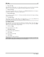
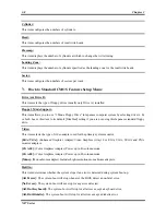
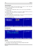
Power Supply Controller:
This option allows you to switch between the default and user-defined voltages. Leave this setting to
default unless the current voltage setting cannot be detected or is not correct. The option “
User Define
”
enables you to select the following voltages manually.
CPU Core Voltage:
This item selects the CPU core voltage.
DDR SDRAM Voltage:
This item selects the voltage for DRAM slot.
LDT Voltage:
This item selects the LDT voltage.
AGP Voltage:
This item selects the voltage for AGP slot.
ATTENTION:
A wrong voltage setting may cause the system unstable or even damage the CPU. Please
leave it to default settings unless you are fully aware of its consequences.
User’s Manual
Summary of Contents for NF7
Page 8: ...1 4 Chapter 1 1 2 Layout Diagram NF7 NF7 S NF7 Series ...
Page 9: ...Introduction 1 5 1 3 Layout Diagram NF7 M User s Manual ...
Page 10: ...1 6 Chapter 1 1 4 Layout Diagram NF7 S2 NF7 S2G Ver 0 22 NF7 Series ...
Page 29: ...Hardware Setup 2 19 NF7 S2 NF7 S2G User s Manual ...
Page 68: ...3 34 Chapter 3 3 34 Chapter 3 NF7 Series NF7 Series ...
Page 72: ...Appendix B B 2 NF7 Series ...
Page 74: ...Appendix C C 2 NF7 Series ...
Page 76: ...D 2 Appendix D NF7 Series ...
Page 84: ...F 4 Appendix F NF7 Series ...

