2-20
Chapter 2
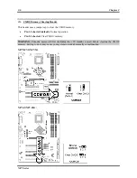
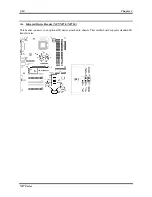
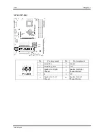
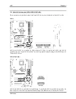
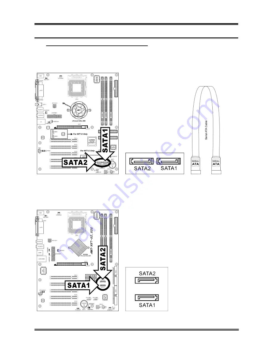
(14). Serial ATA Connectors (NF7-S/NF7-S2/NF7-S2G)
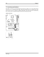
These connectors are provided to attach one Serial ATA device at each channel via Serial ATA cable.
NF7-S:
SATA1 and SATA2 are controlled by Silicon Image PCI Chip. To enable the SATA1 and SATA2
controller, the item “Serial ATA Controller” must be kept enabled (default setting) in the BIOS menu of
“Onboard PCI Device”.
NF7-S2/NF7-S2G:
SATA1 and SATA2 are controlled by South Bridge. To enable the SATA1 and SATA2 controller, the
item “Serial ATA” must be kept enabled (default setting) in the BIOS menu of “OnChip PCI Device”.
NF7 Series
Summary of Contents for NF7
Page 8: ...1 4 Chapter 1 1 2 Layout Diagram NF7 NF7 S NF7 Series ...
Page 9: ...Introduction 1 5 1 3 Layout Diagram NF7 M User s Manual ...
Page 10: ...1 6 Chapter 1 1 4 Layout Diagram NF7 S2 NF7 S2G Ver 0 22 NF7 Series ...
Page 29: ...Hardware Setup 2 19 NF7 S2 NF7 S2G User s Manual ...
Page 68: ...3 34 Chapter 3 3 34 Chapter 3 NF7 Series NF7 Series ...
Page 72: ...Appendix B B 2 NF7 Series ...
Page 74: ...Appendix C C 2 NF7 Series ...
Page 76: ...D 2 Appendix D NF7 Series ...
Page 84: ...F 4 Appendix F NF7 Series ...

