background image

Installing and commissioning

20

Installing and commissioning

41/18-77 EN

b) For rotary actuators

-

Press and hold 

ENTER

.

-


is 

displayed.

-

Wait until the display has changed to


-

Release 

ENTER

.

-

Press and hold 

ENTER


again


until the countdown has run down from 3 to 0.

-

Release 

ENTER

.

Autoadjust is started automatically, and the progress is displayed as in P1.1.

When  Autoadjust has completed successfully, the determined parameters are saved
automatically, and the remote level is activated again.

If any errors should occur during Autoadjust, the respective error code is displayed as in
P1.1. In this case press 

ENTER

 to acknowledge. The operating level, mode 1.3 

(MAN-SENS) will be activated automatically, then. 

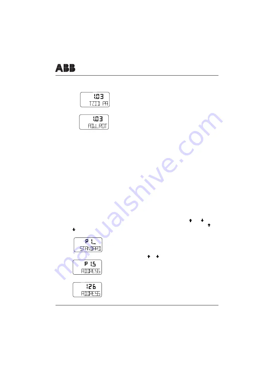
3.4.2 Setting the bus address

When the positioner is on the remote level, first change over to the operating level by
pressing and holding 

MODE

 and 

ENTER

 simultaneously until the countdown has

run down from 3 to 0. Release 

MODE

 and 

ENTER

The positioner changes over

to the operating level.

Switch the positioner over to the configuration level: Press and hold   and   simulta-
neously and then additionally briefly press and release 

ENTER

 once. Keep   and

 pressed until the countdown from 3 to 0 is finished (approx. 3 seconds) and only

then release them. Otherwise, the change-over to the configuration level will fail.

 is 

displayed

Press and hold 

MODE

. Additionally press   or   until

 is displayed

Release 

M

ODE

 is displayed (factory setting)

conf

mA

%

C

°

conf

mA

%

C

°

conf

mA

%

C

°

conf

mA

%

C

°

conf

mA

%

C

°

Summary of Contents for TZIDC-110

Page 1: ...TZID C110 Intelligent positioner for PROFIBUS PA Short manual 41 18 77 EN Rev 01...

Page 2: ...other subjects like configuration operation and ordering details please refer to Data sheet 10 18 0 23 EN or the Operating manual CD version 42 18 74 EN Copyright 2002 by ABB Automation Products GmbH...

Page 3: ...CE compliance information 3 3 Installing and commissioning 4 3 1 Mechanical mounting 4 3 1 1 General 4 3 1 2 Operating conditions at the installation site 5 3 1 3 Mounting to linear actuators 5 3 1 4...

Page 4: ...mmissioning procedure 19 3 4 2 Setting the bus address 20 3 4 3 Overview of the operating modes and how to select from operating level 21 3 4 4 Parameter setting example 22 4 Technical data 24 4 1 Bas...

Page 5: ...ions standards and directives referred to in these operating instructions are applicable in Germany When using the TZID C110 positioner outside the German Fed eral jurisdiction the relevant regulation...

Page 6: ...s symbol is printed next to notes containing important informationen pertai ning to your TZID C110 or its operation Only qualified persons may mount electrically and pneumatically connect and commissi...

Page 7: ...When receiving the delivery please immediately check items and scope for damages and completeness The scope of delivery is stated in the shipping documents If ordered the accessories e g mounting mat...

Page 8: ...rows 2 When mounting ensure that the transfer of the stroke or rotation angle for the posi tion feedback is correct The maxi mum rotation angle is 60 for mounting to linear actuators and 120 for mount...

Page 9: ...available for mounting the positioner to a linear actuator according to DIN IEC 534 lateral mounting to NAMUR comprising the following parts Tools required Wrench 10 mm 13 mm Allen key 4 mm Lever 1 0...

Page 10: ...lip the spring 2 onto the bolt with the follower pin 1 Slip the plastic washer 3 onto the bolt and compress the spring with it Insert the bolt with com pressed spring into the oblong hole in the lever...

Page 11: ...counter nut 4 at the lever Hold the preassembled TZID C110 with the angle bracket 5 still loose in such a way against the actuator that the follower pin on the lever introduces into the follower guide...

Page 12: ...the columnar yoke 2 Insert the U bolts 3 from the inner side of the columnar yoke through the thru holes in the angle bracket Slip on the plain washers 4 spring washers 5 and nuts 6 Hand tighten nuts...

Page 13: ...point is shifted to the inside the stroke range is increased shifting to the outside decreases the range The fine adjustment of the link point is done automatically later during Autoadjust Decrease s...

Page 14: ...ng kit is available Tools required Wrench 10 mm 13 mm Allen key 3 mm Namur feedback shaft adapter 1 0 Four screws M6 1 1 four spring washers 1 2 and four plain washers 1 3 for fastening the mounting b...

Page 15: ...the home position as well as the direction of rotation it must be determined in which position the feedback shaft 1 of the posi tioner must be pre adjusted and in which position the adapter 2 must be...

Page 16: ...25 and 23 26 see the instructions in document 42 18 74 EN delivered to you on a CD ROM M5 Screws After mounting check whether the positioner operates within the permissible range Apply air to the act...

Page 17: ...in case of malfunctions the positioner s max admissible operating pressure of 6 bar 90 psi is not exceeded Otherwise the positioner and or the actuator can be damaged Do not exceed the maximum operat...

Page 18: ...es with the dimension 6x1 mm for the pneumatic piping The amount of supply pressure has to be matched to the working pressure necessary for the actuation The values 1 4 and 6 bar are the limit values...

Page 19: ...ered with your positioner into the appro priate hole in the bottom plate of the case as seen in the illustration below Use a wrench to fasten the cap Do not use a screw driver Make sure that the splas...

Page 20: ...up and the operation of explosion proof installations if explosion proof devices are used Warning Exclusively connect the PROFIBUS PA line to the bus terminals 11 and 12 When connecting a power source...

Page 21: ...Service switch for shut down module 3 Terminals for the plug in module for the shutdown function 4 Kit for digital position feedback either proximity switches or 24 V microswitch first connector termi...

Page 22: ...ng the plug in module Remove 7 10 mm 1 4 3 8 of the cable insulation Insert the wire ends from the top into the corresponding screw terminal and hand tighten the screws access from the side Fig 7 Term...

Page 23: ...its mechanical limit stops in both directions and note the values The angle of rotation is indicated in degrees 4 Return to the remote level Press and hold MODE and ENTER Wait until the countdown has...

Page 24: ...evel mode 1 3 MAN SENS will be activated automatically then 3 4 2 Setting the bus address When the positioner is on the remote level first change over to the operating level by pressing and holding MO...

Page 25: ...rom the operating level to the remote level press and hold MODE and ENTER simultaneously until the countdown has run down from 3 0 Release MODE and ENTER The positioner returns to the remote level 3 4...

Page 26: ...n the TZID C is operating remote controlled 1 Cange over from the remote level to the operating level Press and hold MODE and ENTER simultaneously Wait until the countdown has run down from 3 to 0 Rel...

Page 27: ...nd hold MODE In addition 1 x briefly press is displayed Release MODE Briefly press to select NV_SAVE Press and hold ENTER until the displayed countdown from 3 to 0 has run down The positioner saves th...

Page 28: ...n speed 31 25 Kbit second Operating voltage Bus powered 9 0 32 0 volts Max withstand voltage 35 V Current consumption 10 5 mA Fault current 15 mA 10 5 mA 4 5 mA Name Physical device tag TZID C110 PNO...

Page 29: ...0 of total travel 20 Air supply Instrument air free of oil water and dust to DIN ISO 8573 1 pollution and oil contents according to Class 3 Purity max particle size 5 m max particle density 5mg m3 Oil...

Page 30: ...ilities Ambient temperature 40 to 85 C 40 to 185 F for operation storage and transport Relative humidity 75 95 for a short time non condensing Case Material surface Aluminum protection IP 65 NEMA 4x B...

Page 31: ...40 C Tamb 50 C T6 40 C Tamb 40 C Signal current circuit for Profibus PA only for connection to a certified intrinsically safe circuit e g FISCO power unit oder barrier with the following max values FI...

Page 32: ...ndicator disk Cover with transparent dome Symbol stickers Extension for the feedback shaft Kit for digital position feedback with proximity switches 2 proximity switches for min and max position posit...

Page 33: ...Certificates 41 18 77 EN Certificates 29 5 Certificates...

Page 34: ...Certificates 30 Certificates 41 18 77 EN...

Page 35: ...41 18 77 EN 31...

Page 36: ...Certificates 32 Certificates 41 18 77 EN...

Page 37: ...41 18 77 EN 33...

Page 38: ...Certificates 34 Certificates 41 18 77 EN...

Page 39: ...41 18 77 EN 35...

Page 40: ...SHUT OFF Shut off value OFF 0 1 45 0 OFF P2 5 RAMP UP Setpoint ramp up OFF 0 1 999 9 sec OFF P2 6 RAMP DN Setpoint ramp down OFF 0 1 999 9 sec OFF P2 7 EXIT Return to operat level Action P3 _ ACTUATOR...

Page 41: ...7 7 Y OFF DN Y offset down Y Min 100 0 24 0 P7 8 not used not used not used P7 9 TOL_BAND Tolerance band X 10 20 0 30 P7 10 TEST Test Action P7 11 EXIT Return to operat level Action P8 _ P9 _ P 10_ no...

Page 42: ...ration Level conf conf conf conf conf conf MODE ENTER conf PI STANDARD P2 SETPOINT P3 ACTUATOR P6 MAN_ADJ P7 CTRL_PAR PII FS IP PI 0 PI I PI 2 PI 3 PI 4 P1 5 P1 6 P2 0 n u P2 I n u P2 2 P2 3 P2 4 P2 5...

Page 43: ......

Page 44: ...and disseminating it in any form whatsoever even editings or excerpts thereof especially as reprint photomechanical or electronic reproduction or storage on data processing systems or networks is not...

Reviews: