ABB RMC-100 Startup Manual Download Page 17


2105551-001 rev. AC | 

17


IMPORTANT NOTES: 

Call the ABB main office number listed on the 

back page of this guide for questions about mounting the solar panel 
on the top or side of a meter house. 

Exercise caution when handling the solar panel to avoid damaging it. 

For optimum charging, avoid placing the solar panel where it will be in 
shadows for any part of the day. 

Mount the solar panel facing up from the horizon at a 50°angle. For 
northern hemispheres, position the solar panel facing south. For 
southern hemispheres, position the solar panel facing north.  

Clean the solar panel on a regular basis to ensure maximum charging. 

The hardware required to connect the solar panel to the RMC is: 

—  One solar panel with an integrated cable 
—  One solar panel mounting kit 


CAUTION – Equipment damage. 

Never connect the solar panel or 

alternate charger cable to the RMC before the battery is connected to 
the BAT port (Figure 8, 

Battery


port

).  

To connect the solar panel charger (adapt instructions if connecting to a NEC Class 
2 rated power source as a charger): 
1.  Verify that the solar panel is operating properly before installation: 

a.  Check the solar panel using a digital voltmeter to verify polarity and output 

voltage. Voltage varies depending on the amount of sun, angle to sun, etc. 

b.  If the measured output voltage is within the manufacturer’s specification as 

defined by the specification sheet supplied with the panel, continue with the 
installation. 

c.  If the measured voltage is out of specification, call the ABB main office 

number listed on the back page of this guide for a replacement panel. 

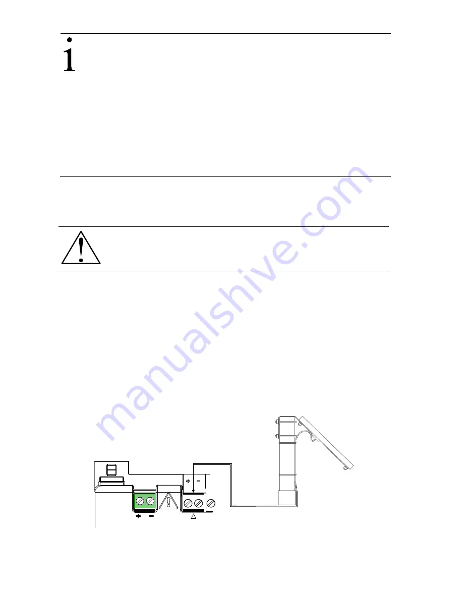
2.  Connect the solar panel cable to the CHARGER/EXT PWR terminals as shown 

in Figure 9. Observe the polarity (+ and -). 

BAT

CHARGER/EXT PWR

Solar 

panel


Figure 9: Solar panel connection 

3.  Continue to section 5.4, 

Lithium battery

Summary of Contents for RMC-100

Page 1: ...Modular Controller 100 will be referred to as the RMC or the controller unless otherwise indicated WARNING Bodily injury equipment damage Although there may be alternate methods of installation and co...

Page 2: ...information Although ABB provides functionality testing on the products and updates that it releases the customer should institute its own testing program for any product updates or other major system...

Page 3: ...TION Property damage minor injury This symbol in conjunction with the signal word CAUTION indicates a potentially dangerous situation Failure to observe this safety information may result in minor or...

Page 4: ...e rated at least Type 3R according to the environment For Class I Zone 2 installations the RMC 100 shall be installed inside an enclosure tested for IP54 in accordance with IEC 60529 and IEC 60079 15...

Page 5: ...If a solar panel is used decide where and how to install the solar panel outdoors For optimum charging avoid placing the solar panel where it will be in shadows any part of the day 2 5 Wiring require...

Page 6: ...re powering the RMC DANGER Damage to health risk to life property damage Allowing the RMC components to make contact with a non insulated tool or without a proper grounding device could create a stati...

Page 7: ...ser Manual 4 3 Wiring COMM ports Wire the RMC COMM ports to communicate with and power external devices Wiring for communication depends on the type of serial interface required by the device Wiring f...

Page 8: ...section CAUTION Equipment damage An external device can be powered from pin 1 VOUT or pin 3 Sw VOUT on both COMM1 and COMM2 The output voltage at these pins is dependent upon the external power suppl...

Page 9: ...n is dependent upon the external power supply connected to the CHARGER EXT PWR port Before connecting to these pins ensure that the external device is compatible with the input voltage at the CHARGER...

Page 10: ...3 GND Input ground 2 1 PWR Power 4 1 PWR Power 2 AI Input signal 2 AI Input signal 3 GND Input ground 3 GND Input ground AI 1 2 3 4 1 2 3 1 2 3 1 2 3 1 2 3 Figure 3 Analog input pinouts 4 4 2 Analog o...

Page 11: ...ignal DI DO 2 5 1 SIG Signal DI DO 5 2 GND ground 2 GND ground 3 1 SIG Signal DI DO 3 6 1 SIG Signal DI DO 6 2 GND ground 2 GND ground DI DO 1 2 3 4 5 6 1 2 1 2 1 2 1 2 1 2 1 2 Figure 6 Digital I O pi...

Page 12: ...s 1 Attach the TFIO module to the DIN rail 2 Attach the TFIO interface cable to the first TFIO module 3 Attach the next TFIO module to the DIN rail 4 Position it beside the previously attached module...

Page 13: ...Before connecting to these pins make sure that the external device is compatible with the input voltage at the CHARGER EXT PWR port Table 8 TFIO valve control interface module M2 J1 J2 J3 J4 1 POINT 1...

Page 14: ...1 J Wht K Yel TC2 J Wht K Yel TC3 J Wht K Yel TC4 J Wht K Yel 3 TC1 Red TC2 Red TC3 Red TC4 Red 4 Shield Shield Shield Shield Table 13 TFIO RTD module M2 J1 J2 J3 J4 1 OUT OUT OUT OUT 2 3 4 IN IN IN I...

Page 15: ...ing of the super capacitor Once the capacitor is fully charged the boot time is considerably less IMPORTANT NOTE In the event of a loss of power or reset the charged super capacitor prevents the suppl...

Page 16: ...gure 8 Battery port 3 Confirm that the battery is supplying power to the RMC by observing the power on sequence information scrolling on the LCD see details in section 5 1 Power on sequence When the D...

Page 17: ...e solar panel or alternate charger cable to the RMC before the battery is connected to the BAT port Figure 8 Battery port To connect the solar panel charger adapt instructions if connecting to a NEC C...

Page 18: ...EXT PWR Figure 10 External power supply connection 3 Apply power to the external power supply 4 Confirm that the RMC is receiving power by observing the power on sequence information scrolling on the...

Page 19: ...2 are not compatible It is assumed that PCCU32 is already installed in the PC or laptop used to connect to the controller To download the latest PCCU32 version see the Additional Information section F...

Page 20: ...he computer USB port that the cable is connected to 7 Click Close 8 On the PCCU32 tool bar click Entry to connect to the device When the connection is successful the PCCU32 Entry screen displays 9 If...

Page 21: ...e ID Location 24 digit alphanumeric The location identifier describes the location such as the county name or a road number Not mandatory Date Time MM DD YYYY HH MM SS 24 hour clock Date and time must...

Page 22: ...en The security codes cannot be configured if the status is on 4 Type a four digit security code for Security Code Level 1 read only access 5 Type a four digit security code for Security Code Level 2...

Page 23: ...rator slash dash or period 4 Select the preferred Time Separator colon or period 5 Click Send to save all of the station settings 7 Configuring communications 7 1 Configuring the COMM ports The config...

Page 24: ...identify the port 10 Configure the Serial port settings to match the settings of the external device IMPORTANT NOTES The Interface setting for a modem is RS 232 Modem If the protocol selected in the...

Page 25: ...he XMV Interface is chosen to support this type of connection Figure 19 Serial port configuration to connect XMVs Figure 20 provides a communication configuration example to connect equipment for remo...

Page 26: ...ynamic addressing change the Enable DHCP field to Yes e If using static addresses type each of the parameters IP Address Default Gateway and Subnet Mask f Click Send An Information box displays a mess...

Page 27: ...input configuration The analog input configuration consists of setting the AI to support the specific type measurement and operating range of the external device To reflect the external device s AI va...

Page 28: ...libration 1 Select I O System on the navigation tree 2 Select the Analog Output tab Figure 24 Figure 24 Analog output configuration 3 Enter the AO percentage or the engineering units number 4 Click Se...

Page 29: ...ue 5 Click Send 8 5 Pulse input configuration Each pulse input has a debounce filter Without debounce the PI operates at a frequency range of 0 to 20 kHz With debounce the frequency range is 0 to 100...

Page 30: ...sabled by default To verify or enable communication with TFIO modules 1 On the navigation tree under the I O System a If modules were installed in TFIO A select TFIO A Modules Figure 27 The TFIO Modul...

Page 31: ...thium battery LC Low Charger Displayed if the battery charging voltage is 0 4 Vdc or is less than or equal to battery voltage If 0 4 Vdc battery charging voltage is greater than battery voltage LC is...

Page 32: ...ing Close signal is being sent to the valve actuator Valve RMC override conditions met DP SP override set point or Low Battery LL Local Lock out is initiated Measurement application H Hold displayed w...

Page 33: ...2105551 001 rev AC 33 Notes...

Page 34: ...34 2105551 001 rev AC This page left intentionally blank...

Page 35: ...2105551 001 rev AC 35 This page left intentionally blank...

Page 36: ...is document The original US English version of this manual shall be deemed the only valid version Translated versions in any other language shall be maintained as accurately as possible Should any dis...

Reviews: