


16
| 2105551-001 rev. AC
WARNING – Bodily injury and property damage.
Do not allow the
battery terminals or cable ends if attached, to come in contact with any
metal surface. When the positive and negative battery terminals
contact a conductive material, this creates a short circuit and could
result in sparks, property damage, and possible explosion.
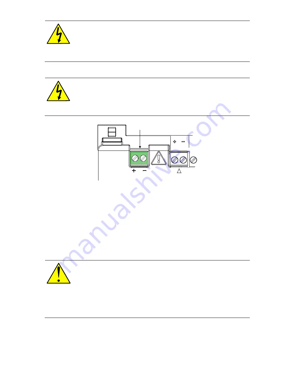
2. Connect the battery to the terminals (Figure 8). The power terminal block is
green. Observe the polarity (+ and -).
WARNING – Bodily injury and property damage.
All wiring of
peripheral or external devices to the controller should be completed
prior to applying power (connecting the battery).
Connect the battery before connecting the charger cable.
BAT
CHARGER/EXT PWR
Battery port
Figure 8: Battery port
3. Confirm that the battery is supplying power to the RMC by observing the power
on sequence information scrolling on the LCD (see details in section 5.1,
Power
on sequence)
. When the DATE/TIME display, the sequence is complete.
4. If the power on sequence fails to initiate or complete, press the reset button
shown in Figure 11.
5.2.2 Connecting the charger
The RMC may use a 10, 20, or 30 watt solar panel with Nominal 12 Vdc output
voltage. The solar panel may be mounted on a 2 inch pipe or the top or side of a
meter house.
WARNINGS – Equipment damage.
Alternate installations could use a
NEC Class 2 rated power source instead of a solar panel charger.
When using a NEC Class 2 rated power source, the output must be
14.5 Vdc to 15.5 Vdc maximum as described in section 2.2,
Battery
and charger requirements
.
Failure to use chargers that meet the required voltage specifications
may cause equipment damage.


