background image

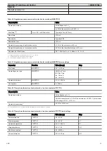
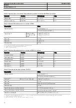
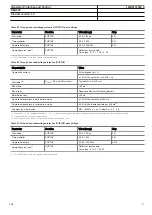
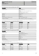
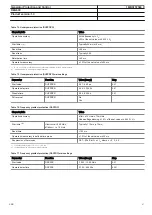
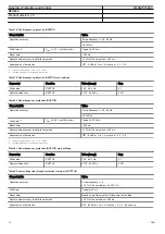
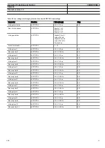
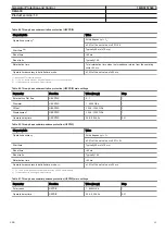
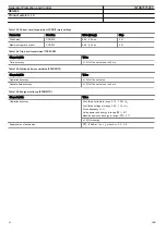
Table 96. Operation characteristics

Parameter

Value (Range)

Operating curve type

1 = ANSI Ext. inv.
2 = ANSI Very. inv.
3 = ANSI Norm. inv.
4 = ANSI Mod inv.
5 = ANSI Def. Time
6 = L.T.E. inv.
7 = L.T.V. inv.
8 = L.T. inv.
9 = IEC Norm. inv.
10 = IEC Very inv.
11 = IEC inv.
12 = IEC Ext. inv.
13 = IEC S.T. inv.
14 = IEC L.T. inv
15 = IEC Def. Time
17 = Programmable
18 = RI type
19 = RD type

Operating curve type (voltage protection)

5 = ANSI Def. Time
15 = IEC Def. Time
17 = Inv. Curve A
18 = Inv. Curve B
19 = Inv. Curve C
20 = Programmable
21 = Inv. Curve A
22 = Inv. Curve B
23 = Programmable

Generator Protection and Control

1MRS757583 C

REG630


Product version: 1.3


ABB

47

Summary of Contents for Relion 630 Series

Page 1: ...RELION 630 SERIES Generator Protection and Control REG630 Product Guide...

Page 2: ...g data 57 22 Accessories 59 24 Tools 60 25 Supported ABB solutions 61 26 Terminal diagrams 63 27 References 65 28 Functions codes and symbols 66 29 Document revision history 69 Disclaimer The informat...

Page 3: ...ation systems 2 Application REG630 provides main protection for generator and generator transformer units in for example small and medium power diesel gas hydroelectric combined heat and power CHP and...

Page 4: ...G 3Ith T G 51BF 51NBF 3I Io BF 51P 1 51P 2 3I 3I 51V I U 59 3U 59G Uo 60 FUSEF 67N 1 67N 2 Io Io 81U 81O 81R f f f t 87G 87M 3dl G M 3I Io Io 3I 3U REG630 Preconf A ANSI IEC 27 3U 32R 32O P 32U P 40 X...

Page 5: ...49T G 3Ith T G 51BF 51NBF 3I Io BF 51N 1 Io 51P 1 51P 2 3I 3I 59 3U 59G Uo 60 FUSEF 64R Io R 81U 81R f df dt GUID C93D2D3A 8C8E 40CB 9242 FA76FA0E3C3D V1 EN Figure 2 Generator in block connection wit...

Page 6: ...32O P 49T G 3Ith T G 51BF 51NBF 3I Io BF 51P 1 51P 2 3I 3I 59 3U 59G Uo 60 FUSEF 64R Io R GUID 42A3A43D 4F62 4541 AB39 D662B21769AB V1 EN Figure 3 Medium sized generator in block connection with a tra...

Page 7: ...ific application changing of the default parameter settings configuration of the default alarms and event recorder settings including the texts shown in the HMI configuration of the LEDs and function...

Page 8: ...e and fault recorders IED self supervision Local Remote push button on LHMI Sequence event recorder User management WebHMI 3I FUSEF 60 U U Uo A Fixed or detached LHMI is available I O 94 CBCM CBCM MEA...

Page 9: ...RTD mA measurement optional Analog interface types A B C Current transformer 5 7 1 8 Voltage transformer 4 3 2 1 One of available current transformer inputs is sensitive 0 1 0 5 A Q 3U 32Q 27 3I 50P 5...

Page 10: ...ve sequence overcurrent protection for machines 2 2 Three phase thermal overload protection two time constants 1 1 Three phase current inrush detection 1 Transformer differential protection for two wi...

Page 11: ...MI presentation 10 Selector mini switch 10 Pulse counter for energy metering 4 Event counter 1 Supervision and monitoring Runtime counter for machines and devices 1 Circuit breaker condition monitorin...

Page 12: ...impedance based restricted earth fault protection underimpedance protection line back up protection thermal overload protection negative phase sequence protection frequency protection and underpower p...

Page 13: ...lay signals such as a protection start or trip signal or an external relay control signal over a binary input can be set to trigger the recording In addition the disturbance recorder settings include...

Page 14: ...gn Engineer and User Administrator The user group association for each individual user enables the use of theprotection relay according to the profile of the user group 16 Inputs and outputs The prote...

Page 15: ...nd binary signals to other protection relays so called horizontal communication using the IEC 61850 8 1 GOOSE Generic Object Oriented Substation Event profile Binary GOOSE messaging can for example be...

Page 16: ...h special time synchronization wiring IRIG B Inter Range Instrumentation Group Time Code Format B IEC 60870 5 103 serial communication has a time stamping resolution of 10 ms Table 6 Supported communi...

Page 17: ...um load of auxiliary voltage supply 35 W Ripple in the DC auxiliary voltage Max 15 of the DC value at frequency of 100 Hz Maximum interruption time in the auxiliary DC voltage without resetting the pr...

Page 18: ...Voltage withstand Continuous 425 V AC For 10 s 450 V AC Burden at rated voltage 0 05 VA 1 Residual current 2 Phase currents or residual current Table 10 Binary inputs Description Value Operating range...

Page 19: ...peration accuracy temperature 1 C Pt and Ni sensors for measuring range 40 C 200 C and 40 C 70 C ambient temperature 2 C CU sensor for measuring range 40 C 200 C in room temperature 4 C CU sensors 40...

Page 20: ...ms at U 48 110 220 V DC 1 A 0 3 A 0 1 A Minimum contact load 100 mA at 24 V AC DC Table 14 Power output relays with TCS function Description Value Rated voltage 250 V DC Continuous contact carry 8 A...

Page 21: ...erial interface characteristics Wave length Fibre type Connector Permitted path attenuation Distance 820 nm MM 62 5 125 ST 4 dB km 1000 m 820 mm MM 50 125 ST 4 dB km 400 m 660 mm 1 mm Snap in 10 m Tab...

Page 22: ...h at 55 C 16 h at 85 C IEC 60068 2 2 Cold test 96 h at 25 C 16 h at 40 C IEC 60068 2 1 Damp heat test cyclic 6 cycles at 25 55 C Rh 93 IEC 60068 2 30 Storage test 96 h at 40 C 96 h at 85 C IEC 60068 2...

Page 23: ...EC 61000 4 3 level 3 IEC 60255 22 3 Fast transient disturbance tests IEC 61000 4 4 IEC 60255 22 4 class A All ports 4 kV Surge immunity test IEC 61000 4 5 level 3 2 IEC 60255 22 5 Communication 1 kV l...

Page 24: ...e test value Reference Dielectric tests IEC 60255 5 IEC 60255 27 Test voltage 2 kV 50 Hz 1 min 500 V 50 Hz 1 min communication Impulse voltage test IEC 60255 5 IEC 60255 27 Test voltage 5 kV 1 2 50 s...

Page 25: ...2005 EN 60255 1 2009 Table 28 EMC compliance Description Reference EMC directive 2004 108 EC Standard EN 50263 2000 EN 60255 26 2007 Table 29 RoHS compliance Description Complies with RoHS directive...

Page 26: ...0 96 Retardation time 30 ms Operate time accuracy in definite time mode 1 0 of the set value or 20 ms Operate time accuracy in inverse time mode 5 0 of the theoretical value or 20 ms 3 Suppression of...

Page 27: ...able Table 32 Voltage dependent overcurrent protection PHPVOC Characteristic Value Operation accuracy At the frequency f fn Current 1 5 of the set value or 0 002 In Voltage 1 5 of the set value or 0 0...

Page 28: ...e set value or 0 002 In at currents in the range of 0 1 10 In 5 0 of the set value at currents in the range of 10 40 In Voltage 1 5 of the set value or 0 002 Un Phase angle 2 Start time1 2 IFault 2 0...

Page 29: ...range of 0 1 10 In 5 0 of the set value at currents in the range of 10 40 In Start time 1 2 EFIPTOC IFault 2 set Start value Typically 12 ms 5 ms EFHPTOC IFault 2 set Start value Typically 19 ms 5 ms...

Page 30: ...e or 0 002 In at currents in the range of 0 1 10 In 5 0 of the set value at currents in the range of 10 40 In Voltage 1 5 of the set value or 0 002 Un Phase angle 2 Start time 1 2 DEFHPDEF and DEFLPTD...

Page 31: ...acteristics table Table 40 Third harmonic based stator earth fault protection H3EFPSEF Characteristic Value Operation accuracy At the frequency f fn 5 of the set value or 0 004 Un Start time 1 2 Typic...

Page 32: ...or earth fault protection MREFPTOC Characteristic Value Operation accuracy At the frequency f fn 1 5 of the set value or 0 002 In Start time1 2 Typically 25 ms 15 ms Reset time 50 ms Reset ratio Typic...

Page 33: ...art value MNSPTOC 0 01 0 50 pu 0 01 Operating curve type MNSPTOC ANSI Def Time IEC Def Time Inv Curve A Inv Curve B Operate delay time MNSPTOC 0 10 120 00 s 0 01 Cooling time MNSPTOC 5 7200 s 1 Table...

Page 34: ...0 00 s 0 001 Table 52 Transformer differential protection for two winding transformers TR2PTDF Characteristic Value Operation accuracy At the frequency f fn 1 5 of the set value or 0 002 In Operate ti...

Page 35: ...ted Winding 1 Winding 2 Winding 1 and 2 Clock number TR2PTDF Clk Num 0 Clk Num 1 Clk Num 2 Clk Num 4 Clk Num 5 Clk Num 6 Clk Num 7 Clk Num 8 Clk Num 10 Clk Num 11 Table 54 High impedance or flux balan...

Page 36: ...pe MPDIF 1 2 1 High operate value MPDIF 100 1000 1 Low operate value MPDIF 5 30 1 Slope section 2 MPDIF 10 0 50 0 0 1 End section 1 MPDIF 0 100 1 End section 2 MPDIF 100 300 1 Table 58 Three phase ove...

Page 37: ...time mode 1 0 of the set value or 20 ms Operate time accuracy in inverse time mode 5 0 of the theoretical value or 20 ms3 Suppression of harmonics DFT 50 dB at f n fn where n 2 3 4 5 1 Start value 1 0...

Page 38: ...600 pu 0 001 Operate delay time PSPTOV 0 040 120 000 s 0 001 Table 64 Positive sequence undervoltage protection PSPTUV Characteristic Value Operation accuracy At the frequency f fn 1 5 of the set valu...

Page 39: ...e Range Step Start value NSPTOV 0 010 1 000 pu 0 001 Operate delay time NSPTOV 0 040 120 000 s 0 001 Table 68 Residual overvoltage protection ROVPTOV Characteristic Value Operation accuracy At the fre...

Page 40: ...rate delay time DQPTUV 0 1 300 00 s 0 01 Min reactive power DQPTUV 0 01 0 50 pu 0 01 Min PS current DQPTUV 0 02 0 20 pu 0 01 Pwr sector reduction DQPTUV 0 0 10 0 1 0 Table 72 Reverse power directional...

Page 41: ...UPPDPR 0 00 60 00 s 0 01 Pol reversal DUPPDPR No Yes Table 76 Frequency gradient protection DAPFRC Characteristic Value Operation accuracy df dt 10 Hz s 10 mHz s Undervoltage blocking 1 5 of the set v...

Page 42: ...ault 0 99 set Start value Typically 190 ms Reset time 190 ms Operate time accuracy in definite time mode 1 0 of the set value or 30 ms Suppression of harmonics DFT 50 dB at f n fn where n 2 3 4 5 1 Fr...

Page 43: ...LVRTPTUV 0 00 1 20 pu 0 01 Recovery time 3 LVRTPTUV 0 00 300 00 s 0 01 Voltage level 4 LVRTPTUV 0 00 1 20 pu 0 01 Recovery time 4 LVRTPTUV 0 00 300 00 s 0 01 Voltage level 5 LVRTPTUV 0 00 1 20 pu 0 0...

Page 44: ...Range Step Leakage React OEPVPH 0 0 50 0 Zb 0 1 Start value OEPVPH 100 200 UB f 1 Time multiplier OEPVPH 0 1 100 0 0 1 Operating curve type OEPVPH ANSI Def Time IEC Def Time OvExt IDMT Crv1 OvExt IDMT...

Page 45: ...os Det Ena UEXPDIS 0 1 1 Diameter UEXPDIS 1 6000 Zb 1 Offset UEXPDIS 1000 1000 Zb 1 Displacement UEXPDIS 1000 1000 Zb 1 Operate delay time UEXPDIS 0 06 200 00 s 0 01 Table 90 Three phase underimpedanc...

Page 46: ...B fail trip mode CCBRBRF 1 Off 2 Without check 3 Current check Retrip time CCBRBRF 0 00 60 00 s 0 01 CB failure delay CCBRBRF 0 00 60 00 s 0 01 CB fault delay CCBRBRF 0 00 60 00 s 0 01 Table 94 Multip...

Page 47: ...Norm inv 10 IEC Very inv 11 IEC inv 12 IEC Ext inv 13 IEC S T inv 14 IEC L T inv 15 IEC Def Time 17 Programmable 18 RI type 19 RD type Operating curve type voltage protection 5 ANSI Def Time 15 IEC D...

Page 48: ...ic Value Operation accuracy At the frequency f fn Voltage 1 0 or 0 002 Un Frequency 10 mHz Phase angle 2 Reset time 50 ms Reset ratio Typically 0 96 Operate time accuracy 90ms 0 ms Generator Protectio...

Page 49: ...0 In 5 0 at currents in the range of 10 40 In Operate time accuracy 1 0 of the set value or 20 ms Traveling time measurement 10 ms Table 101 Fuse failure supervision SEQRFUF Characteristic Value Opera...

Page 50: ...aracteristic Value Operation accuracy 1 0 of the set value Operate time accuracy 1 0 of the set value or 40 ms Table 106 Energy monitoring EPDMMTR Characteristic Value Operation accuracy At all three...

Page 51: ...asurement phase to phase VPPMMXU Characteristic Value Operation accuracy At the frequency f fn 0 5 or 0 002 Un at voltages in the range of 0 01 1 15 Un Suppression of harmonics DFT 50 dB at f n fn whe...

Page 52: ...onics DFT 50 dB at f n fn where n 2 3 4 5 Table 113 Sequence current measurement CSMSQI Characteristic Value Operation accuracy At the frequency f fn 1 0 or 0 002 In at currents in the range of 0 01 4...

Page 53: ...ured value or 0 004 Un in measured voltages 2 0 Un Operation value 1 0 of the Ud or 0 004 Un for Us 1 0 Un Operate time accuracy in definite time mode 1 1 0 of the set value or 0 11 s Operate time acc...

Page 54: ...back raise V OLATCC 0 80 1 60 pu 0 01 Cir current limit OLATCC 0 10 5 00 pu 0 01 LDC limit OLATCC 0 00 2 00 pu 0 01 Lower block tap OLATCC 36 36 1 Raise block tap OLATCC 36 36 1 LDC enable OLATCC FALS...

Page 55: ...20 Mounting methods By means of appropriate mounting accessories the standard relay case for the 630 series protection relays can be flush mounted semi flush mounted or wall mounted Detachable HMI is...

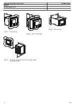
Page 56: ...g 252 5 270 6 8 180 101 6 13 366 GUID 945D3C86 A432 4C1F 927A A208E0C1F5F6 V2 EN Figure 9 Wall mounting 224 265 9 220 25 5 177 258 6 13 GUID A368C5C3 D4A9 40B7 BD0E 181A6BB7ECA6 V1 EN Figure 10 6U hal...

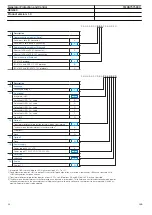
Page 57: ...n A for directly connected generator set N None Pre conf Available analog input options Available binary input output options A AB 7I I0 1 5 A 3U BB 7I I0 1 5 A 3U 8mA RTD in 4mA out AA 14 BI 9 BO AB...

Page 58: ...4 B All options3 4 Z None N 15 Option 2 None N 16 Power supply Power supply 48 125 VDC A Power supply 110 250 VDC 100 240 VAC B 17 Reserved Undefined X 18 Version Version 1 3 D 1 Integrated HMI is not...

Page 59: ...e mounting wall for one 6U half 19 housing the protection relay 1KHL400200R0001 Overhead ceiling mounting kit with cable space for one 6U half 19 housing the protection relay 1KHL400464R0001 Table 119...

Page 60: ...rowser based user interface is used the protection relay can be accessed either locally or remotely using a web browser IE 7 0 or later For security reasons the web browser based user interface is dis...

Page 61: ...ntal GOOSE messaging Compared to traditional hard wired inter device signaling peer to peer communication over a switched Ethernet LAN offers an advanced and versatile platform for power system protec...

Page 62: ...BB solutions Product Version Grid Automation Controller COM600 3 5 or later MicroSCADA Pro SYS 600 9 3 FP1 or later System 800xA 5 1 or later Generator Protection and Control 1MRS757583 C REG630 Produ...

Page 63: ...T VT VT CT CT X1 LAN 1 1 Optional 2 100 BaseTx RJ 45 100 BaseFx LC 3 100 BaseTx RJ 45 Power over Ethernet 2 3 X0 LAN HMI VT Uaux 3 1 2 X329 1 2 3 IRF X9 Fiber optic plastic transmitter TX 1 RX Fiber o...

Page 64: ...e 13 630 series BIO module option Table 125 BIO options Unit BI BO 4U X319 X3161 X324 X321 6U X324 X3211 X329 X326 X334 X331 X339 X336 1 Occupied by RTD module when ordered Generator Protection and Co...

Page 65: ...n portal offers you information about the distribution automation product and service range You will find the latest relevant information on the REG630 protection relay on the product page Scroll down...

Page 66: ...protection MREFPTOC Io R 64R Negative sequence overcurrent protection for machines MNSPTOC I2 G M 46G 46M Three phase thermal overload protection two time constants T2PTTR 3Ith T G 49T G Three phase...

Page 67: ...t indication DPGGIO Single point indication SPGGIO Generic measured value MVGGIO Logic Rotating Switch for function selection and LHMI presentation SLGGIO Selector mini switch VSGGIO Pulse counter for...

Page 68: ...mples A2RADR ACH2 ACH2 Analog channels 21 30 calc val A3RADR ACH3 ACH3 Analog channels 31 40 calc val A4RADR ACH4 ACH4 Binary channels 1 16 B1RBDR BCH1 BCH1 Binary channels 17 32 B2RBDR BCH2 BCH2 Bina...

Page 69: ...n date Product version History A 2012 08 29 1 2 First release B 2014 12 03 1 3 Content updated to correspond to the product version C 2019 02 25 1 3 Content updated Generator Protection and Control 1M...

Page 70: ...70...

Page 71: ......

Page 72: ...BB Distribution Solutions Distribution Automation P O Box 699 FI 65101 VAASA Finland Phone 358 10 22 11 www abb com mediumvoltage www abb com relion Copyright 2019 ABB All rights reserved 1MRS757583 C...

Reviews: