6.2 Opening
When the bottom coil is energized, the magnetic flux generated opposes the force generated
by the magnet assembly. This reduces the holding force, the armature is released and the coil
attracts the armature to the bottom plate. Once there, it is held open by the magnet.
7.0 OPERATIONAL CHECK PRIOR TO INSTALLATION
The breaker should be tested for mechanical and electrical operation before delivery to the
installation site. Make the necessary control power connections. Open the door of the low
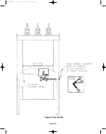
voltage (LV) compartment to observe the mechanical operations. A manual trip handle is
provided on the outside of the cabinet. (See Figure 8)
7.1 Electrical Close and Open
Observe the position-indicator located on the front of the actuator cover plate. If the panel is
green, the breaker is open, and if the panel is red, the breaker is closed. To perform a close
or open, ensure the “Ready” light is illuminated above the Close (1), and Open (0), buttons.
Press the appropriate button firmly, keeping hands and loose clothing clear of operating
linkages. Nothing will happen if the open button is pressed if the breaker is already open and
conversely for close.
Note: In the event of a malfunction or loss of source voltage, the “Ready” light will not be
illuminated.
7.2 Vacuum Test
Make an over-voltage test on each phase assembly to verify that there has been no loss of
vacuum in transportation or handling. Experience has indicated that while a vacuum
interrupter with the vacuum seal intact will withstand 37.5 kVAC across the open contacts for
one minute, the same interrupter open to normal atmosphere will flashover at the gap at a
much lower voltage.
Page 5
38-929M-15A 10/15/02 1:11 PM Page 9
Summary of Contents for R-MAG Series
Page 2: ...38 929M 15A 10 15 02 1 11 PM Page 2 ...
Page 4: ...38 929M 15A 10 15 02 1 11 PM Page 4 ...
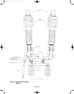
Page 15: ...Page 11 Figure 3 Interrupter Assembly 1200 A 38 929M 15A 10 15 02 1 11 PM Page 15 ...
Page 16: ...Page 12 Figure 4 Interrupter Assembly 2000 A 38 929M 15A 10 15 02 1 11 PM Page 16 ...
Page 17: ...Page 13 Figure 5 Interrupter Assembly 3000 A 38 929M 15A 10 15 02 1 11 PM Page 17 ...
Page 20: ...Figure 8 Trip Handle Page 16 38 929M 15A 10 15 02 1 11 PM Page 20 ...
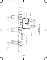
Page 21: ...Figure 9 High Voltage Cabinet Layout Page 17 38 929M 15A 10 15 02 1 11 PM Page 21 ...
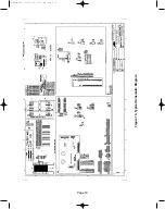
Page 22: ...Figure 10 Typical Schematic Diagram Page 18 38 929M 15A 10 15 02 1 11 PM Page 22 ...
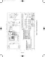
Page 23: ...Figure 11 Typical Connecting Diagram Page 19 38 929M 15A 10 15 02 1 11 PM Page 23 ...
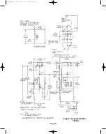
Page 24: ...Figure 12 Typical Outline 1200 A Page 20 38 929M 15A 10 15 02 1 11 PM Page 24 ...
Page 25: ...Figure 13 Typical Outline 2000 3000 A Page 21 38 929M 15A 10 15 02 1 11 PM Page 25 ...
Page 30: ...Page 26 38 929M 15A 10 15 02 1 11 PM Page 30 ...
Page 44: ...Page 40 ILLUSTRATION 8 READY LED OFF 38 929M 15A 10 15 02 1 11 PM Page 44 ...
Page 45: ...Page 41 ILLUSTRATION 9 CB WILL EITHER NOT OPEN OR CLOSE 38 929M 15A 10 15 02 1 11 PM Page 45 ...


