9.0 INSPECTION, MAINTENANCE AND ADJUSTMENT
The R-MAG is an extremely simple device and will require minimal maintenance depending
on the frequency of operation and local environmental conditions.
The safety and successful functioning of any apparatus or system connected with the breaker
depends to a large extent on the proper and reliable operation of the unit.
To provide long reliable service, the breaker must have systematic inspection at regular intervals.
Operating experience based on environmental conditions, the number of operations, magnitude
of current and any unusual operation which occurs, will soon establish a maintenance schedule
which will give assurance of proper breaker reliability. The following check list is a minimum guide.
1. Check the phase assemblies for external damage and clean if contamination is evident.
2. Lubricate wear points and all pins in linkage assemblies with grease.
3. Check contact wear. As a vacuum interrupter continues to perform, material from the butt
contacts is gradually eroded away, and the moving contact is driven deeper into the
interrupter by the operating mechanism. The over-travel spring at the upper end of the
operating rods ensures that proper contact pressure is maintained in the closed position.
Contact erosion reduces the compression of the over-travel spring, which in turn
increases the contact travel. (Total travel of the actuator is fixed.) See 9.2 steps 9-11 for
minor adjustments.
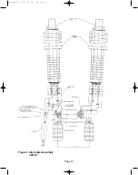
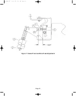
Contact wear can be visually inspected. A line is scribed on the moving contact stem
0.08” from VI end guide. When the line reaches the VI end guide, replace vacuum
interrupters. Figures 3-7 and Procedures 9.1 and 9.2.
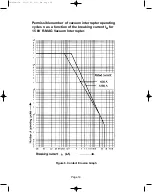
Contact wear can also be monitored by interruption magnitudes and quantity.
4. Verify that the breaker operates correctly using the electrical controls.
5. A Hi-Pot test can be made to verify the vacuum integrity.
RADIATION WARNING: High voltage applied across an open gap in a vacuum can produce
X-radiation. No radiation is emitted when the breaker is closed since no gap exists. Also,
when the breaker is open to the specified contact spacing in service or tested within the
voltages specified, X-radiation at one meter is below the level of concern. A danger could
exist at voltages above or contact spacing below that specified on the nameplate.
A. With the breaker in the open position, jumper both sets of three top terminals. Ground one
set of terminals and the housing. Connect the high voltage to the other set of terminals.
B. Stand clear more than one meter before energizing the high voltage source.
C. Do not exceed 37.5 kV.
Page 8
38-929M-15A 10/15/02 1:11 PM Page 12
Summary of Contents for R-MAG Series
Page 2: ...38 929M 15A 10 15 02 1 11 PM Page 2 ...
Page 4: ...38 929M 15A 10 15 02 1 11 PM Page 4 ...
Page 15: ...Page 11 Figure 3 Interrupter Assembly 1200 A 38 929M 15A 10 15 02 1 11 PM Page 15 ...
Page 16: ...Page 12 Figure 4 Interrupter Assembly 2000 A 38 929M 15A 10 15 02 1 11 PM Page 16 ...
Page 17: ...Page 13 Figure 5 Interrupter Assembly 3000 A 38 929M 15A 10 15 02 1 11 PM Page 17 ...
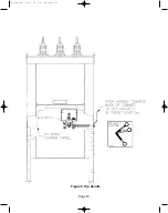
Page 20: ...Figure 8 Trip Handle Page 16 38 929M 15A 10 15 02 1 11 PM Page 20 ...
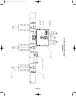
Page 21: ...Figure 9 High Voltage Cabinet Layout Page 17 38 929M 15A 10 15 02 1 11 PM Page 21 ...
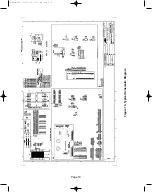
Page 22: ...Figure 10 Typical Schematic Diagram Page 18 38 929M 15A 10 15 02 1 11 PM Page 22 ...
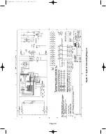
Page 23: ...Figure 11 Typical Connecting Diagram Page 19 38 929M 15A 10 15 02 1 11 PM Page 23 ...
Page 24: ...Figure 12 Typical Outline 1200 A Page 20 38 929M 15A 10 15 02 1 11 PM Page 24 ...
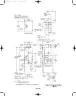
Page 25: ...Figure 13 Typical Outline 2000 3000 A Page 21 38 929M 15A 10 15 02 1 11 PM Page 25 ...
Page 30: ...Page 26 38 929M 15A 10 15 02 1 11 PM Page 30 ...
Page 44: ...Page 40 ILLUSTRATION 8 READY LED OFF 38 929M 15A 10 15 02 1 11 PM Page 44 ...
Page 45: ...Page 41 ILLUSTRATION 9 CB WILL EITHER NOT OPEN OR CLOSE 38 929M 15A 10 15 02 1 11 PM Page 45 ...


