
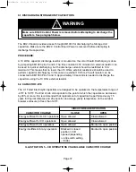


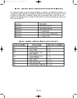

5.0 BINARY OUTPUTS
Binary outputs are simply pairs of mechanical wipe relay contacts. They can be employed to
switch in other circuitry or to an alarm indicator. See Illustration 3 and 4 for the power
limitations of the contacts. Notice the flat curve for AC voltage in Illustration 4. On the inside of
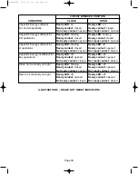
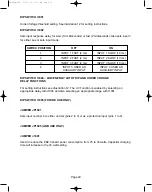
the low voltage cabinet there is a membrane style button plate that contains a “Ready” LED.
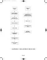
The Ready light will either flash or turn off depending on the state of the Capacitor voltage,
Coil continuity, and the state of the position sensors. The “Unit Ready” output contact can be
used to alarm for the more serious of the three types of problems, but will not signal for all
levels of the above problems. See Illustration 6.
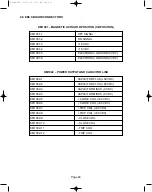
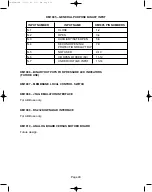
5.1 CIRCUIT BREAKER OPENED (KM1004 Pins 1 and 2)
The Circuit Breaker Opened contacts are normally open. They close only when the circuit
breaker is in the Open position.
5.2 CIRCUIT BREAKER CLOSED (KM1004 Pins 3 and 4)
The Circuit Breaker Closed contacts are normally open. They close only when the circuit
breaker is in the Closed position.
5.3 CIRCUIT BREAKER AUXILIARY OPEN (KM1004 Pins 5 and 6)
The Circuit Breaker Auxiliary Open contacts which close whenever the breaker is in the Open
position.
5.4 CIRCUIT BREAKER AUXILIARY CLOSED (KM1004 Pins 7 and 8)
Additional set of normally open contacts which close whenever the breaker is in the Close
position.
5.5 UNIT READY (KM1004 Pins 9 and 10)
These contacts are normally open. They close when the breaker is ready. They are used to
monitor capacitor charge (O-CO operation ready), valid circuit breaker position, and coil
continuity.
5.6 UNIT NOT READY (KM1004 Pins 11 and 12)
The Unit Not Ready contacts are normally closed. They open when the Unit is Ready. These
contacts are the inverse (negative) of the Unit Ready contacts.
5.7 CIRCUIT BREAKER REMOTE OPEN (KM1004 Pins 13 and 14)
The Circuit Breaker Remote Open contacts are referred to as the “Fleeting Output Contacts.”
This means that they only close for 100 milliseconds after a Remote Operation is performed.
Page 34
38-929M-15A 10/15/02 1:11 PM Page 38
Summary of Contents for R-MAG Series
Page 2: ...38 929M 15A 10 15 02 1 11 PM Page 2 ...
Page 4: ...38 929M 15A 10 15 02 1 11 PM Page 4 ...
Page 15: ...Page 11 Figure 3 Interrupter Assembly 1200 A 38 929M 15A 10 15 02 1 11 PM Page 15 ...
Page 16: ...Page 12 Figure 4 Interrupter Assembly 2000 A 38 929M 15A 10 15 02 1 11 PM Page 16 ...
Page 17: ...Page 13 Figure 5 Interrupter Assembly 3000 A 38 929M 15A 10 15 02 1 11 PM Page 17 ...
Page 20: ...Figure 8 Trip Handle Page 16 38 929M 15A 10 15 02 1 11 PM Page 20 ...
Page 21: ...Figure 9 High Voltage Cabinet Layout Page 17 38 929M 15A 10 15 02 1 11 PM Page 21 ...
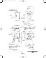
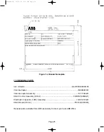
Page 22: ...Figure 10 Typical Schematic Diagram Page 18 38 929M 15A 10 15 02 1 11 PM Page 22 ...
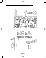
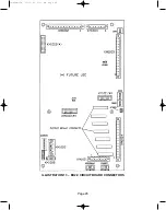
Page 23: ...Figure 11 Typical Connecting Diagram Page 19 38 929M 15A 10 15 02 1 11 PM Page 23 ...
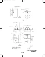
Page 24: ...Figure 12 Typical Outline 1200 A Page 20 38 929M 15A 10 15 02 1 11 PM Page 24 ...
Page 25: ...Figure 13 Typical Outline 2000 3000 A Page 21 38 929M 15A 10 15 02 1 11 PM Page 25 ...
Page 30: ...Page 26 38 929M 15A 10 15 02 1 11 PM Page 30 ...
Page 44: ...Page 40 ILLUSTRATION 8 READY LED OFF 38 929M 15A 10 15 02 1 11 PM Page 44 ...
Page 45: ...Page 41 ILLUSTRATION 9 CB WILL EITHER NOT OPEN OR CLOSE 38 929M 15A 10 15 02 1 11 PM Page 45 ...


