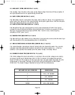

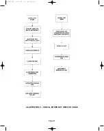


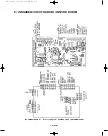
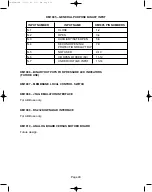


KM1003 – AUXILIARY SUPPLY AND AUXILIARY CAPACITOR CONNECTION
The capacitor voltage is present between KM1003-4 (negative) and KM1003-6 (positive). An
on-board 10 kOhm capacitor is available on KM1003-5. To discharge the capacitors, connect
a jumper from KM1003-5 to KM1003-4. Make sure the Auxiliary power is first removed. To
speed up the discharge time a 10 Ohm 25 watt resistor can be jumpered directly across any
one of the capacitors.
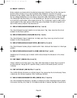
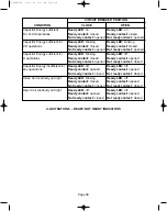
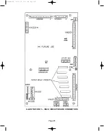
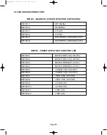
KM1004 - GENERAL PURPOSE BINARY OUTPUT CONTACTS
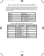
KM1003-1
NOT USED
KM1003-2
AUXILIARY SUPPLY
KM1003-3
AUXILIARY SUPPLY
KM1003-4
- V CAPACITOR
KM1003-5
+ V CAP 10 kOhm RESISTOR
KM1003-6
+ V CAPACITOR
OUTPUT NUMBER
OUTPUT NAME
KM1004 PIN NUMBERS
N.1
CB OPENED
1-2
N.2
CB CLOSED
3-4
N.3
CB OPENED BY AUX
5-6
TRIP SIGNAL
N.4
CB CLOSED BY AUX
7-8
CLOSE SIGNAL
N.5
UNIT READY
9-10
N.6
UNIT NOT READY
11-12
N.7
CB OPENED BY REMOTE
13-14
Page 47
38-929M-15A 10/15/02 1:11 PM Page 51
Summary of Contents for R-MAG Series
Page 2: ...38 929M 15A 10 15 02 1 11 PM Page 2 ...
Page 4: ...38 929M 15A 10 15 02 1 11 PM Page 4 ...
Page 15: ...Page 11 Figure 3 Interrupter Assembly 1200 A 38 929M 15A 10 15 02 1 11 PM Page 15 ...
Page 16: ...Page 12 Figure 4 Interrupter Assembly 2000 A 38 929M 15A 10 15 02 1 11 PM Page 16 ...
Page 17: ...Page 13 Figure 5 Interrupter Assembly 3000 A 38 929M 15A 10 15 02 1 11 PM Page 17 ...
Page 20: ...Figure 8 Trip Handle Page 16 38 929M 15A 10 15 02 1 11 PM Page 20 ...
Page 21: ...Figure 9 High Voltage Cabinet Layout Page 17 38 929M 15A 10 15 02 1 11 PM Page 21 ...
Page 22: ...Figure 10 Typical Schematic Diagram Page 18 38 929M 15A 10 15 02 1 11 PM Page 22 ...
Page 23: ...Figure 11 Typical Connecting Diagram Page 19 38 929M 15A 10 15 02 1 11 PM Page 23 ...
Page 24: ...Figure 12 Typical Outline 1200 A Page 20 38 929M 15A 10 15 02 1 11 PM Page 24 ...
Page 25: ...Figure 13 Typical Outline 2000 3000 A Page 21 38 929M 15A 10 15 02 1 11 PM Page 25 ...
Page 30: ...Page 26 38 929M 15A 10 15 02 1 11 PM Page 30 ...
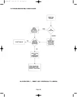
Page 44: ...Page 40 ILLUSTRATION 8 READY LED OFF 38 929M 15A 10 15 02 1 11 PM Page 44 ...
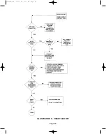
Page 45: ...Page 41 ILLUSTRATION 9 CB WILL EITHER NOT OPEN OR CLOSE 38 929M 15A 10 15 02 1 11 PM Page 45 ...


