


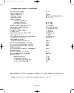
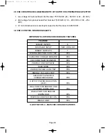
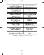


10.0 R-MAG ELECTRICAL SPECIFICATIONS
Rated Maximum Voltage
15.5 kV
Voltage Range Factor, K
1.0
Full Wave Withstand
110 kV
Continuous Current
800 A/1200 A/2000 A/3000 A
Temperature Range
50°C - 70° C
Dielectric Strength
Low Frequency Withstand
Dry 60 Hz 1 minute
50 kV RMS
Wet 60 Hz 10 seconds
45 kV RMS
Minimum Creep to Ground (External)
17.8 Inches
ANSI Standard Operating Duty
O-0.3s-CO-3Min-CO**
Interrupting Time
3.0 cycles (seconds)
Permissible Tripping Delay (Y)
2 seconds
Reclosing Time
0.3 seconds
Short-Circuit (At Contact Part) RMS
*12.5 kA/25 kA
Asymmetry Factor
1.2 RMS
Close and Latch (Initial Current Loop) Peak
*32.5 kA/65 kA
Transient Recovery Voltage
29 kV Peak
(time to peak is 36 µsec)
Load Current Switching Capability
1250 A
Rated Line Charging Breaking Current
100 A
Rated Cable Charging Breaking Current
400 A
Rated Isolated Capacitor Bank Breaking
400 A
(Definite Purpose)
Rated Back-to-Back Capacitor Bank Breaking
400 A
(Definite Purpose)
Rated Capacitor Bank Inrush Making
20 kA
Rated Capacitor Inrush Frequency
4240 Hz
Mechanical Life
Between Servicing
2,000
No-Load Mechanical
10,000
Continuous Current Switching
10,000
Inrush Current Switching
200
*Breaker available as either 12.5 kA (Close and Latch Rating is 32.5 kA) or 25 kA (Close and Latch Rating is 65 kA).
**Operating duty conforms to old ANSI Standard (actual time can be CO-15 Sec-CO).
Page 22
38-929M-15A 10/15/02 1:11 PM Page 26
Summary of Contents for R-MAG Series
Page 2: ...38 929M 15A 10 15 02 1 11 PM Page 2 ...
Page 4: ...38 929M 15A 10 15 02 1 11 PM Page 4 ...
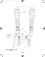
Page 15: ...Page 11 Figure 3 Interrupter Assembly 1200 A 38 929M 15A 10 15 02 1 11 PM Page 15 ...
Page 16: ...Page 12 Figure 4 Interrupter Assembly 2000 A 38 929M 15A 10 15 02 1 11 PM Page 16 ...
Page 17: ...Page 13 Figure 5 Interrupter Assembly 3000 A 38 929M 15A 10 15 02 1 11 PM Page 17 ...
Page 20: ...Figure 8 Trip Handle Page 16 38 929M 15A 10 15 02 1 11 PM Page 20 ...
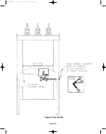
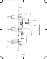
Page 21: ...Figure 9 High Voltage Cabinet Layout Page 17 38 929M 15A 10 15 02 1 11 PM Page 21 ...
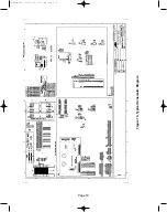
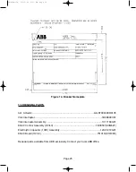
Page 22: ...Figure 10 Typical Schematic Diagram Page 18 38 929M 15A 10 15 02 1 11 PM Page 22 ...
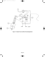
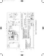
Page 23: ...Figure 11 Typical Connecting Diagram Page 19 38 929M 15A 10 15 02 1 11 PM Page 23 ...
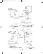
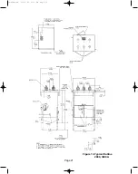
Page 24: ...Figure 12 Typical Outline 1200 A Page 20 38 929M 15A 10 15 02 1 11 PM Page 24 ...
Page 25: ...Figure 13 Typical Outline 2000 3000 A Page 21 38 929M 15A 10 15 02 1 11 PM Page 25 ...
Page 30: ...Page 26 38 929M 15A 10 15 02 1 11 PM Page 30 ...
Page 44: ...Page 40 ILLUSTRATION 8 READY LED OFF 38 929M 15A 10 15 02 1 11 PM Page 44 ...
Page 45: ...Page 41 ILLUSTRATION 9 CB WILL EITHER NOT OPEN OR CLOSE 38 929M 15A 10 15 02 1 11 PM Page 45 ...


