
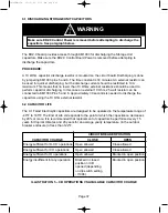
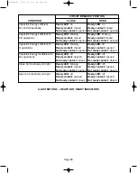
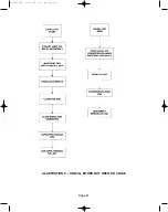


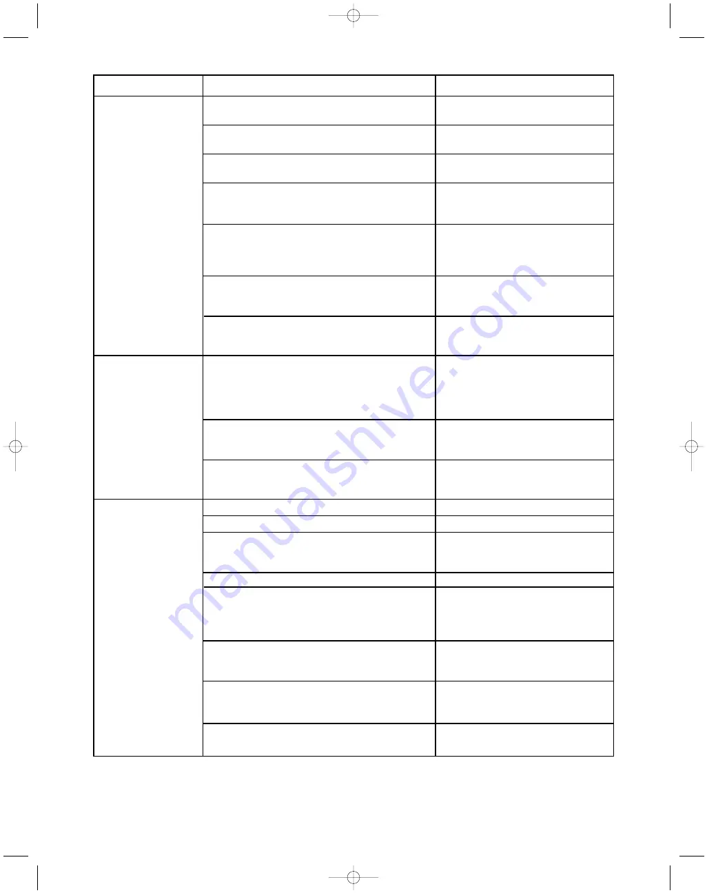
ILLUSTRATION 10 – TROUBLESHOOTING GUIDE
Page 42
PROBLEMS
POSSIBLE CAUSES
POSSIBLE SOLUTIONS
Ready LED is off
The Auxiliary Supply Voltage
Connect the Auxiliary Supply
(unit not ready)
is absent.
Voltage.
The Magnetic Actuator is not connected or
Check the Magnetic Actuator
damaged.
circuit.
The position sensors are not
Check the position sensor circuit.
connected correctly or damaged.
The Under Voltage (UV) function is
Make sure voltage being
enabled and Input is open.
monitored is connected to
UV input.
The Under Voltage function is enabled
Set the correct UV threshold
and the monitored voltage is connected
level via DIP Switch I1001.
to the Under Voltage Input, but the
voltage is lower than the threshold.
The auxiliary supply voltage has been
Connect the auxiliary supply
turned off and the voltage on the capacitor
voltage.
is under the O-CO levels.
The control panel is damaged or not
Verify the control panel
connected correctly.
connections or change if it is
damaged.
Ready LED Blinking
The circuit breaker is closed and
In this case only the opening
the close coil is disconnected or
operation is available; open the
broken.
CB (the Ready LED will be
turned off) and check the
closing coil circuit.
The auxiliary supply voltage has
If the CB is closed you can
been turned off.
perform a CO operation;
connect the auxiliary supply.
During the Start up or after the
Wait a few seconds.
operations, the capacitor bank
is charging.
The closing
The Closing Coil is broken or damaged.
Check the Closing Coil circuit.
command is
One open input is active.
Verify all the open input states.
not performed
The Block in Open input is open (69 switch
Make sure voltage is applied
open or disconnected).
to the Block in Open input and
manual trip lever is raised.
The capacitor bank is not connected.
Check the capacitor bank circuit.
The Ready LED on control panel is off.
If the Ready LED is off, verify
the above conditions under
“Ready LED is off (unit not
ready)”.
The Control panel is damaged or not
Verify the control panel
connected properly.
connections or change it if
damaged.
The energy in the capacitor bank is
Make sure the auxiliary supply
not enough for a CO operation.
voltage is connected. See “ready
light blinking” section above.
The external close input is not supplied.
Verify close command is wired
to input.
38-929M-15A 10/15/02 1:11 PM Page 46
Summary of Contents for R-MAG Series
Page 2: ...38 929M 15A 10 15 02 1 11 PM Page 2 ...
Page 4: ...38 929M 15A 10 15 02 1 11 PM Page 4 ...
Page 15: ...Page 11 Figure 3 Interrupter Assembly 1200 A 38 929M 15A 10 15 02 1 11 PM Page 15 ...
Page 16: ...Page 12 Figure 4 Interrupter Assembly 2000 A 38 929M 15A 10 15 02 1 11 PM Page 16 ...
Page 17: ...Page 13 Figure 5 Interrupter Assembly 3000 A 38 929M 15A 10 15 02 1 11 PM Page 17 ...
Page 20: ...Figure 8 Trip Handle Page 16 38 929M 15A 10 15 02 1 11 PM Page 20 ...
Page 21: ...Figure 9 High Voltage Cabinet Layout Page 17 38 929M 15A 10 15 02 1 11 PM Page 21 ...
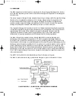
Page 22: ...Figure 10 Typical Schematic Diagram Page 18 38 929M 15A 10 15 02 1 11 PM Page 22 ...
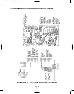
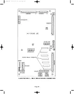
Page 23: ...Figure 11 Typical Connecting Diagram Page 19 38 929M 15A 10 15 02 1 11 PM Page 23 ...
Page 24: ...Figure 12 Typical Outline 1200 A Page 20 38 929M 15A 10 15 02 1 11 PM Page 24 ...
Page 25: ...Figure 13 Typical Outline 2000 3000 A Page 21 38 929M 15A 10 15 02 1 11 PM Page 25 ...
Page 30: ...Page 26 38 929M 15A 10 15 02 1 11 PM Page 30 ...
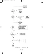
Page 44: ...Page 40 ILLUSTRATION 8 READY LED OFF 38 929M 15A 10 15 02 1 11 PM Page 44 ...
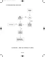
Page 45: ...Page 41 ILLUSTRATION 9 CB WILL EITHER NOT OPEN OR CLOSE 38 929M 15A 10 15 02 1 11 PM Page 45 ...


