ETC 7131A1011, Installation Manual
The ETC 7131A1011 is a high-quality product designed for easy installation in any setting. Make sure to download the free Installation Manual for this product from our website for detailed instructions on how to set it up. A must-have manual for a hassle-free installation experience.
Share
Download


Reviews:
No comments
Related manuals for 7131A1011

L-PKZ0 Series
Brand: Eaton Pages: 2

IZM32
Brand: Eaton Pages: 60

IZM97
Brand: Eaton Pages: 106

Cutler-Hammer Digitrip 1150
Brand: Eaton Pages: 84

IZM20
Brand: Eaton Pages: 8
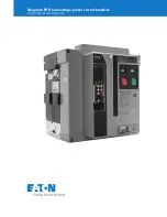
Magnum PXR
Brand: Eaton Pages: 68

LBS-PS11
Brand: ETI Pages: 2

Shortrack 90
Brand: Huntron Pages: 7

MicroVersaTrip PM AK-100
Brand: GE Pages: 26

ReliaGear Pro-Stock Spectra RMS
Brand: GE Pages: 5

ReliaGear Pro-Stock THQB
Brand: GE Pages: 8

GEH-62808
Brand: GE Pages: 2

ML-18H
Brand: GE Pages: 31

ML-14-0
Brand: GE Pages: 36

MicroVersaTrip AK-100
Brand: GE Pages: 32

PowerVac GEK-86132F
Brand: GE Pages: 40

PowerVac GEK-86132G
Brand: GE Pages: 44

PowerVac 5kV VL
Brand: GE Pages: 68


