background image


Installing the LWT 

27

Grounding the instrument

The LWT must be grounded in accordance with national electrical codes, using a protective earth (PE) 
terminal by means of a short connection to an equipotential bonding. The equipotential bonding 
conductor must have a maximum cross-section of 4 mm² (12 AWG).

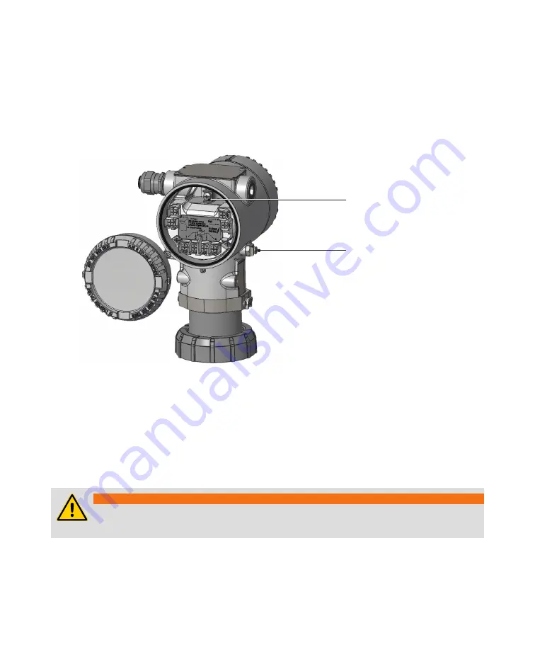
PE terminals are available inside and outside the instrument housing (see Figure 18). Both terminals are 
electrically interconnected.


Figure 18 

Position of the two PE terminals

External PE terminal

Internal PE terminal

If using the external PE terminal, you must 

connect the grounding wire to the monitored vessel.

When grounding the LWT with a shielded wire, connect the wire to the PE terminal located inside the 
housing. 

That shielded wire should only be grounded at one end, not both.

The most effective way to ground the LWT housing is a direct connection to a ground with a maximum 

impedance of 5 mΩ.

Outside installations or installations exposed directly or indirectly to lightning discharges shall have 
a secondary lightning protection module. Use of a protected terminal block in combination with a 
lightning arrestor module is mandatory for the continuous protection of users and installations.

WARNING

The terminal block needs to be replaced if the installation shows any sign of damage 
resulting from direct or indirect lightning discharges.

Summary of Contents for LWT300 series

Page 1: ... USER GUIDE LWT300 series Guided wave radar level transmitter Modbus ...

Page 2: ...d accurate However no guarantee is given or implied that the document is error free or that the information is accurate ABB makes no representations or warranties with regard to the product and instructional and reference materials including but not limited to all implied warranties of merchantability and fitness for a particular purpose ABB does not warrant guarantee or make any representations r...

Page 3: ...necting the instrument 28 Upon startup 31 4 Introducing the user interface Introducing LWT user interfaces 33 Accessing menus 34 Navigating the instrument display 34 5 Configuring the instrument at startup 6 Configuring the instrument Configuring the display 39 Contrast 39 Number of decimals 39 Configuring Operator pages 40 Selecting an Operator page to display 41 Enabling Operator page autoscroll...

Page 4: ...gling communication modes 67 Toggling via HMI 67 Toggling via hardware 68 Configuring Modbus communication 70 Setting the Modbus network address 70 Selecting the communication speed 70 Selecting the parity status 70 Selecting the stop bit 70 Setting the response delay 70 Selecting the register base number 70 Setting the swap mode 71 Configuring HART communication 71 Setting the HART network addres...

Page 5: ...actually proceeding Additionally each chapter in this guide contains descriptions of processes or procedural instructions with their own specific safety information Only by observing all safety information can you minimize the risks of hazards to personnel and or the environment Additional safety information is provided in the LWT300 series Hazardous Location Safety Guide part nº 3KXL001271U0141 D...

Page 6: ...FACES Indicates the presence of heat sufficient enough to cause burns ELECTROSTATIC DISCHARGES Indicates a device or part of a device that is susceptible to electrostatic discharges Identifies any terminal intended for connection to an external conductor for protection against electrical shock in case of a fault or the terminal of a protective earth ground electrode Identifies protective earth con...

Page 7: ... all chemicals involved in the work environment Electrical Connection information in this guide must be observed otherwise the applicable protection type may be affected WARNING Connections may only be performed by authorized personnel in accordance with the provided electrical circuit diagrams In addition involved personnel must observe the relevant safety regulations regarding the installation a...

Page 8: ...ruments will not work if exposed to common mode voltages in excess of the maximum allowed supply voltage Grounding Ground the instrument according to requirements see Grounding the instrument on page 27 WARNING Ensure that the equipment or any device or power cord connected to the instrument is properly grounded If an interruption of the protective earthing connection is suspected make sure that t...

Page 9: ...is the operator s sole responsibility to provide and continuously ensure a secure connection between the product and your network or any other network as the case may be Operators shall establish and maintain any appropriate measures such as but not limited to the installation of firewalls the application of authentication measures the encryption of data the installation of anti virus programs etc...

Page 10: ...ns ABB decided not to password protect the Modbus communication protocol in LWT series instruments General deployment guidelines Limit and control physical access to the device and the network on which it is connected Limit and control access to all Modbus communication tools Use role based access according to needs Change all default passwords and strictly control their dissemination Lock and or ...

Page 11: ...g instructions Read this guide carefully before working with the instrument For personnel and system safety and for optimum performance make sure that you thoroughly understand the contents of this document before installing using or maintaining the instrument This guide does not contain detailed information on all available models or every conceivable event that may occur during setup operation a...

Page 12: ...een the initial pulse and the reflected one the electronics can calculate the product level 5 Since microwave energy travels at the speed of light one complete measurement cycle is made up of several thousand pulses The electronics use the time domain reflectometry TDR sampling technique to reconstruct from these numerous pulses a waveform that can be processed by the microprocessor see Diagnosing...

Page 13: ...ument head Connection ports caps removed Housing cover terminal side Nameplate Housing cover display side Human Machine Interface HMI LCD and buttons External ground connection Ex protection mode identification plate Ex protection mode identification sub plate Housing security screw Coupler adapter Coupler adapter security screw ...

Page 14: ...ser Guide The coupler Figure 3 Typical 3 4 NPT LWT310 instrument coupler Probe attachment thread NPT thread Head coupler thread Head sensor socket Alignment bumpers As shipped Figure 4 Head coupler assembly ...

Page 15: ...wer up see page 28 and configure the instrument see page 39 Modbus specific considerations Using the Modbus protocol allows devices made by different manufacturers to exchange information via the same communication bus without the need for any special interface devices Up to 32 devices can be connected on one Modbus line The Modbus network can be expanded using repeaters NOTICE All Modbus networks...

Page 16: ...writing for any activities beyond this scope Repairs performed by ABB authorized centers are excluded from this article Technical limit values The instrument is designed for use exclusively within the values stated on the name plates and within the technical limit values specified on the data sheets Technical limit values that must be observed at all time are The maximum working pressure ambient w...

Page 17: ...commendations below Install the assembled LWT system probe coupler head assembly see page 26 as far as possible from the fill drain stream When inserting probes avoid internal obstructions such as tubing ladders agitators etc To prevent excessive probe movement in an agitated process or where installation close to the vessel wall is required secure the bottom end of a probe to the vessel Probes in...

Page 18: ...ns For maximum power supply voltage refer to the instrument identification plate For signal and power loop connections up to 1200 meters 4000 feet in length use Ø 0 8 to 0 35 mm 18 to 22 AWG twisted stranded pair wiring Longer loops will require larger wires Supply voltage at the instrument terminals must be between 10 5 and 28 5 V DC Typical power consumption is below 30 mW Cable and cable gland ...

Page 19: ...stallations LWT instruments installed in a non metallic vessel or in open air environments will be subject to interference from other electromagnetic devices e g radios You may need to use stilling wells to eliminate such interferences Also with non metallic vessels use an instru ment equipped with a flange or replace the flange with a metal sheet insert 150 mm 8 in to make contact with the couple...

Page 20: ...e opening the connection to the instrument Any process media released may cause severe injuries Provide adequate protection and training against all chemicals involved in the work environment WARNING Only qualified and authorized personnel should be put in charge of the installation electrical connection commissioning operation and maintenance of the instrument This personnel must hold the necessa...

Page 21: ... one of the probe segments 2 Screw the female end of the end of probe segment on the male end of the first segment and tighten by hand Figure 5 Assembling two segments of a segmented probe Lock 3 Use two wrenches each one holding the probe slot of the segment to apply the recommended torque see below in opposite directions at the same time see Figure 5 on page 17 NOTICE There are two sizes of head...

Page 22: ...s not fall in the vessel by inserting a metal pin not provided in the through hole in such a way that the pin rests across the vessel port 5 Repeat steps 1 to 4 for all the remaining segments until you reach the probe segment that connects to the coupler For more information on attaching the probe to the coupler see Attaching a probe to the coupler on page 19 ...

Page 23: ...ic components NOTICE LWT instruments come in a wide variety of configurations They can come with probes already attached and or external flanges already soldered on or neither The following pages explain the most common procedure although it might have already been performed at the factory To attach a probe on a standard coupler 1 Screw the provided head bolt on the screw in end and tighten by han...

Page 24: ...e slot to apply the recommended torque see below in opposite directions at the same time Figure 9 Tightening the probe NOTICE There are two sizes of head locks 8 9 mm 0 35 in and 13 5 mm 0 53 in The recommended torque as specified by the manufacturer is as follows For the 8 9 mm lock 2 8 N m 2 1 lbf ft For the 13 5 mm lock 13 5 N m 10 0 lbf ft ...

Page 25: ...ween the coupler and the tank If PTFE tape is used it shall be used in a very thin layer to avoid electrically isolating the coupler from the tank If your coupler came in a flanged configuration make sure that the appropriate gasket is installed before inserting the coupler assembly and secure the flange with the appropriate nuts and bolts to the torque required by the flange class Rotating the ho...

Page 26: ... their body before touching electronic components When the head unit is installed it is possible to rotate its HMI in one of four different positions at 90 intervals To rotate the HMI 1 Make sure that the instrument is powered off and that the M4 hex head locking screws are screwed in see Figure 10 2 Unscrew the housing cover on the HMI side hazardous area warnings must be heeded see Safety on pag...

Page 27: ... sure that the four plastic locks are properly fixed NOTICE Be careful not to bend the connection pins see Figure 13 when pushing the board back in Figure 13 Connection pins on back of HMI board Connection pins Plastic locks 6 Hand tighten the housing cover back in place NOTICE For Ex d and or flameproof installations see note Securing housing cover in flameproof explosion proof areas on page 30 ...

Page 28: ...ead on a support bracket in a remote location 3 Connecting the probe coupler assembly to the instrument head with the proper coaxial communication cable The following pages explain the last two steps The support bracket provided with your instrument is designed to be fixed on a pipe It comes with an adapter that links the instrument head and coupler NOTICE The sensor head must not be installed up ...

Page 29: ...n between the coupler and the adapter If PTFE tape is used it shall be used in a very thin layer to avoid electrically isolating the coupler from the adapter Figure 15 Positioning the instrument head on the adapter Head adapter Head adapter security screw 4 Tighten by hand the head adapter on the head coupler adapter 5 Re tighten the head adapter security screw to secure the head adapter 6 Complet...

Page 30: ...al cable we strongly suggest the use of a wrench or pliers The coaxiable cable bend radius shall not be less than 150 mm 6 in Figure 16 Connecting the coaxial cable to the head coupler adapter Coaxial cable 8 Connect the other end of the coaxial cable to the top of the coupler see Figure 17 Figure 17 Connecting the coaxial cable to the top of the coupler ...

Page 31: ...grounding wire to the monitored vessel When grounding the LWT with a shielded wire connect the wire to the PE terminal located inside the housing That shielded wire should only be grounded at one end not both The most effective way to ground the LWT housing is a direct connection to a ground with a maximum impedance of 5 mΩ Outside installations or installations exposed directly or indirectly to l...

Page 32: ... components are sensitive to electrostatic discharges Before performing any connection operators shall make sure that they have discharged all static electricity from their body before touching electronic components NOTICE Ensure that a drip loop 1 water trap is used when installing the connecting cables for the sensor If necessary rotate the transmitter housing as necessary Figure 19 Typical LWT ...

Page 33: ...re 20 on page 29 WARNING Do not handle the instrument by the threaded interface Threaded edges are sharp and could cause personal injuries NOTICE After an interval of several weeks increased force will be required to remove the housing cover This situation is normal it is caused by the type of gasket used 4 Route the connection cable through the cable gland and the open electrical connection port ...

Page 34: ...ations Locking screw tightness Process connection Electrical connection 9 Power up the instrument by switching on the circuit breaker At power on the through the glass TTG touch interface goes through a calibration process For the TTG to work properly it is mandatory that the housing cover be correctly tightened before power on NOTICE For instruments equipped with the through the glass TTG display...

Page 35: ...lay option wait for the HMI calibration process to complete 30 seconds after power on before operating the HMI Figure 21 Instrument LCD on power up Figure 22 Initial Operator page with values based on default configuration NOTICE During the boot process no level information is displayed For more information on Operator pages see Configuring Operator pages on page 40 The next chapter introduces the...

Page 36: ...Page intentionally left blank ...

Page 37: ...tand the access methods to the parameters that you need to change and what to expect when you reach these parameters There are two methods to access the parameters but only access using the instrument HMI is discussed in this user guide Once the LWT instrument is powered up its display looks like this Figure 23 Typical Operator screen Left action item Right action item Left action key Right action...

Page 38: ... stored parameter value Accessing menus Upon selecting the configuration menus icon on the main screen the interface displays a selection of four access levels Read Only Standard Advanced and Service Figure 24 Access Level menu Access level icon All but the Read Only access level require a password if defined When selecting an access level you will be asked for your password By entering the proper...

Page 39: ...ight within a menu 2 Once you find the option that you want to set highlight it by using the arrow keys 3 Press the right action key Edit see Figure 26 on page 35 4 In the Edit screen use the left action key Next to move from left to right over the editable values see Figure 27 on page 35 5 Once you are on the value that you want to modify press the Up or Down arrow key to increase or decrease the...

Page 40: ...Page intentionally left blank ...

Page 41: ...configure your instrument you need to know the following What you want to measure level ullage interface etc The unit in which these measurements must be made meters feet etc The lowest and highest levels that you expect to measure in your vessel The dielectric constant of the vessel content The speed at which the vessel normally fills up or is drained a k a maximum level rate The measurement that...

Page 42: ...alue is set For more information see Changing the empty zero value on page 64 5 Press Next The Full Span screen appears This sets the highest level that you expect to measure in the vessel a Press Edit b Set the required value see Setting a value on page 35 c Press OK The value is set For more information see Changing the full span value on page 65 6 Press Next The Max Level Rate screen appears Th...

Page 43: ...play menu Contrast To set the display contrast 1 Select Display Contrast 2 Press the Up or Down arrow key to increase or decrease the contrast percentage By default the contrast is set to 50 3 Press OK Number of decimals The LWT allows you to set the number of decimals to display on screen for length flow and volume units To set the number of decimals to display for these units throughout the inte...

Page 44: ... of data To configure an operator page 1 Select Display Operator Pages Operator Page n n being the number of the operator page that you want to configure 2 From the Operator Page n screen select Display Mode 3 Press Edit 4 Highlight the display mode that you want and press OK There are seven modes available 1Row 6Char S 1Row 6Char SBar 1Row 9Char 1Row 9Char Bar 2Row 9Char 2Row 9Char Bar 3Row 9Char...

Page 45: ...page is selected and you automatically return to the startup display where the newly selected page appears For more information on configuring the content of Operator pages see Configuring Operator pages on page 40 Enabling Operator page autoscroll The autoscroll feature allows you to move automatically between Operator pages at a set time interval This is useful when you simply want to record spe...

Page 46: ...ntered To define passwords 1 Select Device Setup Access Control Standard Password or Advanced Password 2 Press Edit 3 In the edit window press the Up and Down arrow keys to move right or left on the alphanumerical ribbon and highlight the alphanumerical characters that you need to create the password 4 Press Next to select the highlighted character and move on to the next character to highlight 5 ...

Page 47: ...e procedure but select Enabled instead Preventing unwanted deletion of data To prevent inadvertent or malicious overwriting of an instrument s settings and data you can enable software and or hardware write protection both are disabled by default NOTICE Activating hardware write protection prevents all forms of external access to the instrument Software write protection To enable software write pr...

Page 48: ...driver fully press down on the write protection screw and turn 90 clockwise to activate hardware write protection or if already activated 90 counterclockwise to deactivate it Figure 34 Activating hardware write protection Deactivated write protection default Activated write protection 3 Put the nameplate back in place ...

Page 49: ...ce whereas the last two variables TV and QV allow for monitoring of additional variables Amplitude Electronics Temperature Interface Amplitude GPC Dynamic Factor External Temperature linked to pt100 external temperature sensors see PT100 temperature sensors on page E99 Available variables depend on configuration choices made elsewhere application category linearization status or output type etc 3 ...

Page 50: ... the medium measured The default application category depends on the instrument ordered To set the application category 1 Select Device Setup Sensor Setup Application Category 2 Press Edit 3 Highlight the appropriate application based on medium measured DC or liquid vs solid or the need to measure the interface between two liquids and press OK The interface application is used to measure the heigh...

Page 51: ... g liquid and vapor gas The gas phase compensation GPC feature takes into account the variation of DC brought about by the presence of a substance in gas phase inside a vessel thus considerably improving level measurement accuracy GPC generally applies to high pressure high temperature HPHT applications e g boilers but it can be used in any application where a substance in gas phase is present GPC...

Page 52: ...et and you return to the previous menu Setting up the application Before starting level measurements you need to set certain hardware parameters regarding the probe the vessel and the instrument nozzle These parameters are set in the Application Setup menu under the Device Setup menu Figure 36 The Device Setup menu Changing probe type Your instrument as delivered was configured with the type of pr...

Page 53: ... length Selecting tank type You can set the type of vessel in which the probe will be hanging The type of vessel impacts the quality and nature of the signal sent down the probe The default tank type is Metallic To do so 1 Select Device Setup Application Setup Tank Type 2 Press Edit 3 Select the type of tank in which the probe will be immersed and press OK Setting nozzle length You can set the len...

Page 54: ...nsmitter or should you choose to add a transmitter at a later date you need to toggle the remote transmitter state to represent the new configuration To do so 1 Select Device Setup Application Setup Remote Transmitter 2 Press Edit 3 Highlight On or Off and press OK Setting process conditions You can also set the various conditions occurring inside the tank if you want them to be taken into conside...

Page 55: ...ng maximum level rate The maximum level rate is the rate at which the process will reach its Full limit This influences the processing speed of the instrument The default value is No Filter To set the maximum level rate 1 Select Device Setup Filtering Max Level Rate 2 Press Edit 3 Highlight the appropriate maximum level rate and press OK Setting up a median filter The median filter is designed to ...

Page 56: ...h the instrument considers measured amplitudes as valid A classic use of this threshold value is when for any reason you have a very noisy signal and you do not want that noise to be measured You can achieve this by setting the amplitude threshold above that noise level To set the amplitude threshold 1 Select Device Setup Filtering Amplitude Threshold 2 Press Edit 3 Set the amplitude threshold and...

Page 57: ...K Figure 40 Blocking and safety distances Sensor reference point Nozzle length Blocking distance Safety distance Setting a safety distance The safety distance is a specific distance where you can take measurements at levels preceding the blocking distance in case you might want to be informed when such levels are reached To set a safety distance 1 Select Device Setup Safety Setting Safety distance...

Page 58: ...rference To prevent raising unnecessary alarms you can configure an alarm delay that will let a specified amount of time pass before raising an alarm To set such a delay 1 Select Device Setup Safety Setting Alarm Delay 2 Press Edit 3 Set a value between 0 and 3600 seconds the default is 10 for the delay that you want to allow before the instrument raises alarm and press OK Setting up linearization...

Page 59: ...e level to volume conversion does not progress in a linear fashion because of the irregular shape of the vessel By creating a linearization table with proper values this function allows to compensate for the irregular shape of the vessel In LWT instruments there is an order in which to perform operations and make the feature functional Access the function Set the linearization table Enable the fun...

Page 60: ...inearization Setup Output Unit 2 Press Edit 3 Highlight the level volume or flow unit that will be used with data output from the linearization calculation and press OK Setting maximum level volume or flow value To set the maximum level volume of flow value to measure 1 Select Device Setup Linearization Setup Maximum 2 Press Edit 3 Set the maximum level volume or flow value that the instrument wil...

Page 61: ... To properly configure the linearization feature 1 Select Device Setup Linearization Set LIN Points The 00 linearization point is highlighted see below 2 Press the Left action key to select the measured level In 3 Press the Right action key to edit the In value and press OK when you are done 4 Press the Left action key to select the output associated with the measured level Out 5 Press the Right a...

Page 62: ... values are set to Volume or Flow see Setting variables on page 45 after enabling the linearization function Managing saved linearization tables You can clear an existing linearization table if you want to start from scratch e g if you moved your instrument to a different tank and you can restore the existing table if you want to erase the linearization table under development and reload the saved...

Page 63: ...tup as your default setup you can return to that default user setup at any time To do so 1 Select Device Setup Save Setup reset Reset to User Default 2 Press OK Your current setup is erased and replaced with the default user setup Resetting to factory default Should you be in a situation where the default user setup does not work anymore e g you have moved the LWT instrument to a new vessel you ca...

Page 64: ... configuration and parameterization of intelligent field devices 2 USB RS 485 converter not provided by ABB At end of Modbus interface with 120 Ω resistance between A Tx Rx B Tx Rx 3 RS 485 cable not provided by ABB Half duplex wiring with A Tx Rx B Tx Rx and GND Connect Tx and Rx Connect TX and Rx LWT guided wave radar level transmitters can be configured with the aid of various software communic...

Page 65: ...to CONFIG HART RS485 with the HMI or the dip switches dip switches 3 and 4 to position 1 see Figure 44 below For operating with a Modbus master after configuration the transmitter must be set back to OPERATE MODBUS with the HMI or the dip switches dip switch 4 to position 0 Before starting configuration via a software communication tool the transmitter function must be switched from Operate to Con...

Page 66: ...Page intentionally left blank ...

Page 67: ... will have to recalibrate your instrument and enter new values This can be done in software via the Calibrate menu see Figure 46 or by emptying and then filling the vessel whose level you want to measure The following pages explain how to do this Figure 45 Calibration parameters Full Span Empty Zero Probe length Sensor reference Ullage Level Distance Level offset sensor offset NOTICE Depending on ...

Page 68: ...ue is less than or equal to the full value Changing empty zero value in hardware To set this value in hardware you first need to completely empty the vessel whose level you want to measure Once the vessel is empty and you have inserted the probe in the vessel 1 On the instrument head unscrew and remove the nameplate This exposes two buttons identified Z and S and the write protection screw Figure ...

Page 69: ... Figure 47 on page 64 2 Once the probe is fully deployed press the S button for a few seconds This sets the full span calibration value Adding a level offset A level offset is a distance that you might add and that represents the distance between the bottom of the tank and the empty zero value The default value for this parameter is 0 m The value can be set between 50 and 50 m To set that value 1 ...

Page 70: ...Page intentionally left blank ...

Page 71: ...set from the Communication menu Figure 48 The Communication menu Toggling communication modes LWT300 instruments always operate in one of two modes Operation or Configuration Operation mode is the normal mode for data exchange over the Modbus protocol and Configuration mode is the mode to use when configuring the instrument over the HART protocol These modes can be set either in software of hardwa...

Page 72: ...e energized state Before working on the circuit secure the breaker to prevent any accidental power up In an explosion proof flameproof installation do not remove the covers while the instrument is energized NOTICE DIP switch settings always have priority over HMI settings 1 Make sure that the instrument is powered off and that the M4 hex head locking screws are screwed in see Figure 49 2 Unscrew t...

Page 73: ...S TM P N 3KXL001060U0400 ENABLE DISABLE SW 4 CONFIG HART RS485 OPERATE MODBUS 1 2 3 4 ON Dip switches Configuration HART RS485 Operation Modbus For more information on the configuration setup that you need to start communicating with your instrument see Configuring the LWT300 with a computer on page 60 NOTICE When you are done configuring the instrument remotely via HART you must toggle the commun...

Page 74: ...set the communication protocol parity status 1 Select Communication Modbus Parity 2 Press Edit A list of parity statuses appears No Parity Even Odd 3 From that list select a parity status compatible with your network and press OK Selecting the stop bit To set the communication protocol stop bit 1 Select Communication Modbus Stopbit 2 Press Edit Available stop bits appear 1 2 3 From that list selec...

Page 75: ...wave radar Setting the HART network address To set the instrument address so that it can be identified for configuration purposes with your software tool 1 Select Communication HART Device Address 2 Press Edit 3 Set an address between 0 and 63 and press OK Your instrument can now be identified by your software tool for configuration purposes Locating an instrument with tags A tag is intended to si...

Page 76: ...Page intentionally left blank ...

Page 77: ...cedures indicated in this documentation voids the warranty NOTICE Since the instrument may form part of a safety chain ABB recommends replacing the instrument immediately if any defects are detected Diagnosing problems If the LWT instrument is malfunctioning in any way the LCD displays specific event messages destined to help you identify and understand the situation When an event happens a messag...

Page 78: ... information about the currently diagnosed error you need to access the Diagnostics operator menu To do so 1 From the displayed Operator page press the left action key to access the operator menus 2 Highlight and select Diagnostics Figure 52 The Diagnostic operator screen Alarm group category Alarm code Alarm description NAMUR Classification icon In the error description the error code number is d...

Page 79: ...Figure 54 The Diagnostic History screen Alarm group category Alarm code Alarm description Number of times that the alarm has been activated Time elapsed since alarm was last activated Total time that the alarm has been active NAMUR Classification icon 2 Once you are done browsing press Back Clearing the diagnostic history To clear all diagnostic messages kept in the history 1 From the Diagnostics ...

Page 80: ...6 Invalid device parameters Enter valid parameters F236 017 Sensor NV Failure The sensor should be replaced ASAP S110 018 Successful sensor reboot Successful sensor reboot S062 019 Surface inside blocking distance Check process conditions and device config F237 020 Sensor Board communication error Restart sensor If condition persists call ABB F233 023 Electronics NV Failure The electronics must be...

Page 81: ...ics Class Masking 2 Select the class of events that you want to mask Failures cannot be masked Maintenance Required Check Function Off Specification Info None 3 In the selected class masking select Edit Level or Distance Maintenance Required Enabled and press OK This class of events for the selected application will now be masked Events recorded before activation of this feature are kept in the ev...

Page 82: ...ay The waveform display illustrates the signal traveling along the probe Figure 56 The waveform display 1 2 3 4 5 6 7 8 1 Display of the level LVL distance DIS ullage ULL or interface INT value 2 Display of the blocking distance BLK or safety distance SFD Note This is the only highlighted option that is editable see 4 3 Level or interface marker 4 Exit or Edit indicator 5 Zoom information 6 Refere...

Page 83: ...e measured distance matches the real distance To select the current distance 1 Select Diagnostics Waveform Level Echo Selection or Interface Echo Selection Current Distance The distance of the current level or interface echo appears 2 Press Back Selecting another echo To select the previous or next echo measured on the probe 1 Select Diagnostics Waveform Level Echo Selection or Interface Echo Sele...

Page 84: ...el simulation 1 Select Diagnostics Simulation Level Sim Level Sim 2 Press Edit 3 Set the level value that you want to simulate and press OK 4 Press Back 5 Select Enable and press Edit 6 Press OK The instrument sends level data signals on the network and the value set should appear as a reading on a software communication tool interface Obtaining device status data For commissioning purposes you ma...

Page 85: ...iagnostics Total Run Time The total run time of the instrument is indicated 2 Press Back to return to the Device Status menu Performing a self test Self tests are used to compare the electrical signature of the instrument s PCBs with a factory thumbprint This test is usually performed every two to three years to confirm SIL compliance To perform the self test 1 Select Diagnostics Self Test Start S...

Page 86: ... asked to provide any of the following information available from the Device Info menu Figure 58 The Device Info menu Manufacturer Name Model Device ID Device Serial number Order code Manufacturing date Installation date Last modify date Address City Phone number Hardware revision Software revision ...

Page 87: ...nu item Details Main chapters Access Level page A83 Easy Setup page A83 Device Setup page A84 Display page A84 Calibrate page A86 Diagnostics page A86 Device Info page A87 Communication page A88 Access Level menu Item Logout Read Only Standard Advanced Service Easy Setup menu Item Application Category Set PV PV Unit Empty Zero Full Span Max Level Rate Display Line1 View1 ...

Page 88: ... Unit Temperature Unit Sensor Setup Application Category Gas Phase comp GPC Mode GPC Marker Distance GPC Static Factor GPC Dynamic Factor Upper Media DC Reset Tracking Application Setup Probe Type Probe Length Tank type Nozzle Length Bypass SW pipe Diam End Of Probe Mode Remote Transmitter Process Conditions Buildup Detection Foam Flashing Emulsion Agitated High Vibration Filtering Damping Median ...

Page 89: ... Output Unit Maximum Volume Calculation Cylinder Orientation Cylinder Diameter Cylinder Length Gen Linearization Set Lin Points Saved Tables Clear Restore Save Setup Save Reset Save as user default Reset to user default Global Factory Reset Display menu Item Submenus Contrast Operator pages Operator page 1 Operator page 2 Operator page 3 Operator page 4 Autoscroll Length format Flow format Volume ...

Page 90: ... Ref Point At Level At Distance At End of Probe Record Waveform Level Echo Selection Current Distance Select Previous Echo Select Next Echo Confirm Current Echo Interface Echo Selec Current Distance Select Previous Echo Select Next Echo Confirm Current Echo Diagnostic History Clear History Class Masking Maintenance Req Check Function Off Specification Info None Simulation Distance Sim Level Sim In...

Page 91: ...nic Temp Max Electronic Temp Reset Min Max Total Run Time Self Test Start Self Test Result Self Test Device Info menu Item Manufacturer Name Model Device ID Device Serial Number Order Code Manufacturing Date Installation Date Last Modification Date Address City Phone Number Software revision Hardware revision ...

Page 92: ...nu Item Submenus HART Devices Address Tag Message Last Command Device ID Manufacturer ID Device Type Descriptor Device Revision HART Revision Modbus Address Baud Rate Parity Stopbit RespDelay Time Address Offset Swap Mode Device Mode ...

Page 93: ... 2 2400 3 4800 4 9600 5 19200 4 9600 This is the baudrate used during Modbus communication Parity 202 TABENUM8 0 None 1 Even 2 Odd 0 This is the parity bit in the Modbus frame Stop bit 203 TABENUM8 1 One stop bit 2 Two stop bits 1 This is the number of stop bits in the Modbus frame Map Register Offset 204 TABENUM8 0 0 1 1 1 This offset is added from the address received in the Modbus frame message...

Page 94: ... Reg 3000 Primary Variable in Byte Order of Register 3000 SV 1304 Float32 Reg 3000 Secondary Variable in Byte Order of Register 3000 TV 1306 Float32 Reg 3000 Third Variable in Byte Order of Register 3000 QV 1308 Float32 Reg 3000 Quarternary Variable in Byte Order of Register 3000 Advanced Status 1310 UINT16 The device status is obtained from the first 6 bytes of HART command 48 Advanced Status 131...

Page 95: ...arning with highest priority NOTE The higher the number is higher is the priority Level 1 Top 7001 Float32 Reg 3000 Top Liquid height from bottom Inches Level 2 Interface 7003 Float32 Reg 3000 Interface Liquid height from bottom Inches Temperature 7005 Float32 Reg 3000 Tank Temperature Deg F DIP Switch Status 10000 UINT16 On Board DIP Switch Status HMI Software Revision 10001 UINT16 HMI Software R...

Page 96: ...Page intentionally left blank ...

Page 97: ...65 1 079856 264 507 1 002840 1 005705 1 014456 1 029597 1 062307 1 192220 311 592 1 002418 1 004851 1 012252 1 024933 1 051729 1 147384 1 424747 366 691 1 002036 1 004082 1 010283 1 020834 1 042799 1 116952 1 282623 3 086361 Example with steam resulting error in the gas phase Gas phase Temperatrure Pressure C F 5 bar 72 5 psi 5 bar 72 5 psi 5 bar 72 5 psi 5 bar 72 5 psi 5 bar 72 5 psi 5 bar 72 5 p...

Page 98: ...Page intentionally left blank ...

Page 99: ...9 2 Acetic Acid 20 68 6 2 Acetone 25 77 20 7 Acetophenone 18 Acetyl bromid 16 2 Acetyl chloride 15 9 Acetylacetone 23 Acetylene dibromide 7 2 Acetylene tetrabromide 5 6 Aconite acid ester 6 3 Adipic Acid 1 8 Aerosile 1 0 Aether 4 0 Air at STP for 0 9 MHz 1 00058986 0 00000050 Alcohol allyl 20 6 Alcohol cetyl 60 140 3 6 Alcohol diacetone 18 2 Alcohol ethyl ethanol 25 77 24 3 Alcohol methyl methanol...

Page 100: ... 64 Carbon tetrachloride 20 68 2 23 Castor Oil 15 6 60 4 7 Chlorine chlor fluid 0 32 2 0 Chlor benzene 5 7 Chloroform 20 68 4 8 Coconut oil refined 2 9 Cotton seed oil 3 1 Cresol 17 2 63 10 6 Cumene 20 68 2 4 Decane 20 68 2 0 Diesel oil fuel 2 1 Dodecane 20 68 2 0 Ether 20 68 4 3 Ethylamine 21 1 70 6 3 Ethylene glycol 20 68 37 0 Fish oil 2 6 Fluorbenzene 6 4 Trichlorofluoromethane refrigerant R 11...

Page 101: ... 1 8 Linoleic Acid 0 32 2 6 2 9 Linseed Oil 3 2 3 5 Mercury vapor 148 298 1 00074 Methane 173 280 1 7 Napthalene 20 68 2 5 Octane 20 68 2 0 Oil 2 Olive Oil 20 68 3 1 Oxygen 193 315 1 51 Palmitic Acid 71 1 160 2 3 Palm seed oil 1 8 Paraffin 1 6 Pentane 20 68 1 8 Phenol 10 50 4 3 Pentanol 14 8 Phosgene 0 32 4 7 Phosphorus liquid 3 9 Pinene 20 68 2 7 Propane 0 32 1 6 Propanol CH CH CH OH 20 1 Propyle...

Page 102: ... F Dielectric Constant ε Toluene 2 0 2 4 Transformer oil 2 1 Turpentine wood white spirit 20 68 2 2 Vacuum by definition 1 Vinegar 24 Water 20 68 80 4 Water 360 680 10 Water demineralised 29 3 Water heavy 78 3 Water oil emulsion 24 Wine 25 ...

Page 103: ...aling compound Figure 59 Pt100 terminals PWR 3 4 SURGE INSIDE RTD 1 2 B P N 3KQZ207165U0400 USE WIRING RATED QR code AMBIENT TEMPERATURE 5 C MIN ABOVE MAX COMM A Pt100 temperature sensor terminals NOTICE CONNECTION OF A PT100 TEMPERATURE SENSOR You can simulate an external temperature by using a 100 ohm resistor equivalent to 0 C 32 F with two jumpers installed between the terminals for the Pt100 ...

Page 104: ...Page intentionally left blank ...

Page 105: ...Page intentionally left blank ...

Page 106: ...Page intentionally left blank ...

Page 107: ......

Page 108: ...is document without prior notice With regard to purchase orders the agreed particulars shall prevail ABB does not accept any responsibility whatsoever for potential errors or possible lack of information in this document We reserve all rights in this document and in the subject matter and illustrations contained therein Any reproduction disclosure to third parties or utilization of its contents in...

Reviews: