


Page 15
© 2021 ABB. All rights reserved.
Version 1.0
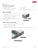
Step 14
-
Configure Controller per Galaxy Pulsar Edge Controller Quick Start
Guide
Verify and edit controller basic configuration parameters per site engineering instructions.
Information: Alarm Card (LEDs and Alarm)
Shelf LEDs and Alarms
Condition
Shelf LED
Shelf Alarm
OK
ALM
Class 2 Circuit On
G
OFF
-
Class 2 Circuit OFF
G
OFF
-
Class 2 Circuit Overcurrent/shorted
OFF
Y
Alarm
Class 2 Circuit Fail (1 or more)
OFF
R
Alarm
Input Voltage Very Low
OFF
OFF
Alarm
Input Voltage Out of Range
OFF
Y BLINK
Alarm
Reversed Input Polarity
OFF
R BLINK
Y BLINK
Alarm
Alarm Card Fail
OFF
R
Alarm
Internal Shelf Comm Fault
3
OFF
G
Alarm
GP Comm Fault
OFF
R BLINK
Alarm
Module LEDs
Condition
Module OK LED
Module Circuit
LEDs
2
1
-
8
Priority
1
LED
Circuit
-
On
G
G
Circuit
-
OFF
G
OFF
Circuit
-
ON
-
Overcurrent
3
Y
Y
Circuit Fail
1
R
R
Comm Fault
-
Alarm Card
4
R BLINK
Per circuit
Condition
Module Fail
1
R
OFF
Input Voltage Out of Range
2
Y BLINK
OFF
Input Voltage Very Low or Reversed
Polarity
OFF
OFF
Table 2: Shelf LED and Alarm
Table 3: Module LED Status
Circuit LED
Figure 16: Alarm Card
Information: Converter Module LEDs
1
OK LED indicates the highest LED priority. Priority 1 is highest.
2
Each Circuit LED indicates the Condition of its Circuit, independently of the other Circuits.
3
Internal Shelf Comm Fault is the loss of communication between the alarm card and 1 or more modules. Possible causes: module removal and module internal
failure.
Replace the module or remove and replaced the Alarm Card to clear the alarm.
Figure 17: Module LEDs
QUICK START GUIDE


