


Page 13
© 2021 ABB. All rights reserved.
Version 1.0
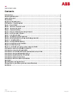
Step 7
-
Install Controller
•
Slide the PS841A_0I6R_USB_DS controller into the left
most slot of the shelf.
•
Secure the controller by snapping it firmly to the shelf
slot.
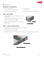
Step 8
-
Install Alarm and LAN Cables
•
The Alarm Connectors are on the rear side of the Shelf.
•
Alarm J5 provides LAN
-
Connect to the Ethernet network.
•
ALARM J3 provides Data connection for Battery temperature and voltage monitor.
•
Alarm J1 and J2 have detachable blocks which can be used to Wire to office alarms and signals.
•
Connect alarm cables to the 10
-
pin Alarm connector.
•
Strip the alarm wire
3/16” .
•
Insert wire fully into wire entry (28
-
16 AWG).
•
Tighten screw with
1/16”
flat screw driver.
•
Insert alarm connector into the chassis.
Figure 11: Controller Installation
J5 LAN Connection
J2 Alarm Connection
J1 Alarm Connection
Figure 12: Alarm Connections
J4
(Not applicable for this System)
J3 Battery Temp and Voltage Monitor
QUICK START GUIDE


