4 Repair
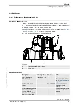
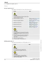
4.8.1. Replacement of gearbox, axis 1-3
153
3HAC022031-001 Revision: C
©
Co
py
rig
h
t 200
4-
200
8 ABB. All righ
ts reser
v
ed.
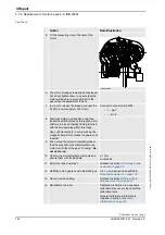
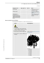
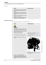
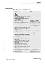
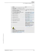
3. Place the gearbox unit upside-down on a table or
similar surface.
4. Fit the base to the gearbox unit and secure with
the 12 screws and washers.
12 pcs; M12x50. Tightening torque:
54 Nm.
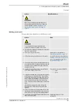
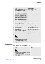
5. Refit the bottom plate to the base.
6. Turn the base and gearbox unit around and
secure to the installation site.
Further detailed in section
and securing the robot on page 47
.
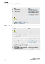
7. Refit the motor, axis 1.
Detailed in section
8. Refit the motor, axis 2.
Detailed in section
9. Refit the motor, axis 3.
Detailed in section
10. Refit the complete lower arm.
Detailed in section
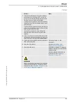
11. Refit the cable unit, axes 1-3.
Detailed in section
.
12. Calibrate the robot.
Calibration is detailed in a separate
calibration manual, enclosed with
the calibration tools.
General calibration information is
included in section
.
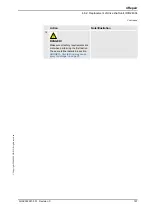
13.
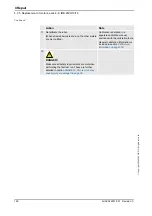
DANGER!
Make sure all safety requirements are met when
performing the first test run. These are further
detailed in section
cause injury or damage! on page 35
Action
Note
Continued
Summary of Contents for IRB 2400/L
Page 1: ...Product manual Articulated robot IRB 2400 L IRB 2400 10 IRB 2400 16 M2000 M2000A M2004 ...
Page 2: ......
Page 8: ...Table of Contents 6 3HAC022031 001 Revision C Copyright 2004 2008 ABB All rights reserved ...
Page 191: ......
Page 192: ......
Page 193: ......
Page 194: ......
Page 195: ......
Page 198: ......
Page 199: ......
Page 202: ......
Page 203: ......
Page 205: ......
Page 226: ......


