Note
Action
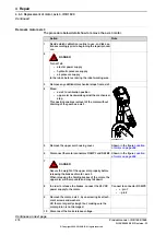
xx1800000171
Reconnect all the connectors to the board.
Be careful not to damage the sockets or pins.
Make sure the connector and its locking arms
are snapped down properly.
6
Verify that the robot cabling is positioned
correctly, according to previously taken pic-
ture/notes.
WARNING
Screened cables must not get in contact with
the brake release board after installation.
Eliminate all risks of contact between
screened cables and the brake release board.
7
Spare part no. is specified in
.
Check the
gasket
of the base cover. Replace
it if damaged.
8
Shown in the figure
.
Refit the base cover.
9
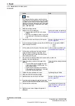
xx0600002777
Refit the centering piece (B) to the push but-
ton unit in order to align it vertically.
Also make sure that the unit is correctly
aligned sideways: the measurements x1 and
x2 in the figure to the right should not differ
more than 1 mm from each other!
10
WARNING
Before continuing any service work, follow
the safety procedure in section
release buttons may be jammed after service
work on page 161
11
Continues on next page
Product manual - IRB 1600/1660
255
3HAC026660-001 Revision: W
© Copyright 2006-2018 ABB. All rights reserved.
4 Repair
4.5.3 Replacing the push button unit
Continued
Summary of Contents for IRB 1600
Page 1: ...ROBOTICS Product manual IRB 1600 1660 ...
Page 8: ...This page is intentionally left blank ...
Page 18: ...This page is intentionally left blank ...
Page 48: ...This page is intentionally left blank ...
Page 152: ...This page is intentionally left blank ...
Page 336: ...This page is intentionally left blank ...
Page 372: ...This page is intentionally left blank ...
Page 388: ...This page is intentionally left blank ...
Page 396: ......
Page 397: ......


