L3447
Emax DC
54/108
L3728
Model
Scale
Page No.
Doc. No.
Apparatus
1SDH000635R0002
13.2.9.9
Load control function
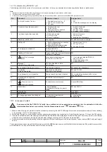
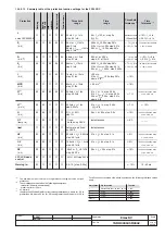
Single loads can be enabled/disabled on the load side before the overload protection L intervenes and trips the circuit-breaker on the supply
side. This is done by contactors or switch-disconnectors (wired outside the release), controlled by the PR123/DC by means of contacts on the
PR120/K module or on the PR021/K external unit.
The current thresholds are lower than those available with the protection L, so that the load control can be used to prevent tripping due to overloads.
The function is active when an auxiliary power supply or power by PR120/V-PR120/LV module is present (see par. 14.1.3).
The operating logic involves the activation of three contacts when the preset thresholds LC1, LC2 and I
w
are exceeded.
Thresholds LC1 and LC2 are expressed as a percentage of I
1
(current threshold specified for protection L) while the "warning current" I
w
is expressed
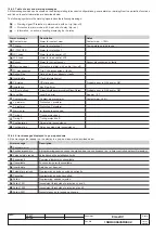
as an absolute value. The allowable values are given in the following table:
Warning current Iw
0.30 ÷ 10.00 step 0.05xIn
Threshold LC1
50% ÷ 100% step 1% xI
1
Threshold LC2
50% ÷ 100% step 1% xI
1
From the PR123/DC you can associate each of the PR120/K or PR121/K contacts with a configuration (NO or NC), a delay and any latch.
13.2.9.10 Voltage protections “UV”, “OV”
The PR123/DC unit provides 2 voltage protections, which can be disabled, with fixed adjustable time (t = k), active both with self-powering and
with auxiliary supply:
– Undervoltage “UV”
– Overvoltage “OV”
Apart from the normal timing and "TRIP" operation, the voltage protections can be in a state defined as "alarm" (with the "emergency" led on and
an alarm message displayed) providing there is an auxiliary or PR120/V or PR120/LV module power supply. In fact, in the case where the circuit-
breaker is open and no current is detected, the timing leads to the "alarm" state and not to "TRIP". This is because the fault linked to the voltages
can persist even with the circuit-breaker open and the unit would therefore always be under "timing". When the circuit-breaker is closed or the
passage of a current is detected, you pass immediately from the state of "alarm" to "TRIP" without timing.
13.2.9.10.1 Protection “UV”
When the minimum voltage drops below the set threshold U
8
the protection counts down the preset time interval t
8
and then opens.
13.2.9.10.2 Protection “OV”
When the maximum voltage exceeds the set threshold U
9
the protection counts down the preset time interval t
9
and then opens.
13.2.9.11 Protection against reverse active power “RP”
The PR123/DC unit provides protection (which can be disabled) with an adjustable fixed time (t = k), against reverse active power, active both
with self-powering and auxiliary supply.
When the total reverse active power (sum of the power of the 2 polarity) exceeds the set reverse active power threshold P
11
the protection counts
down the preset time interval t
11
and then opens.
The minus sign ('-') in front of the threshold and power indicates reverse power. The threshold is indicated as a percentage of "Pn", where "Pn"
is the nominal power of the circuit-breaker.
13.2.9.12 Double protections setting
Using the double protections setting, the PR123/DC can save a set of alternative parameters for all the protections. The second set of parameters
(set B) can replace the default set (set A) by means of an external command. The passage from set A to set B can be made when there is a change
in the mains configuration or when there is an emergency capable of changing the load capacity and the short-circuit levels.
The second set of parameters (set B) can be enabled by:
- digital input provided with the PR120/K module. For instance, it can be connected to an auxiliary contact of a bus-tie;
- communication network, by means of the PR120/D-M (e.g. when the switch is scheduled);
- directly from the user interface on the PR123/DC (see settings menu par. 13.5.4);
- with a time that can be specified by set A or set B after the circuit-breaker has closed;
- depending on a Vaux being installed.
In operation, the state (set A and set B) is indicated on the display.
The double setting is disabled by default. To enable it, see par. 13.5.4.1.

