L3447
Emax DC
10/108
L3728
Doc. No.
Model
Apparatus
Scale
Page No.
1SDH000635R0002
5.1.1
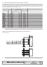
Examples of positioning the connection busbars according to the terminals
The connection busbars enable the connection between the terminals of the circuit-breakers and the busbars of the switchgear. Their sizing must
be carefully studied by the switchgear designer. Some examples of possible constructions are given in this paragraph. The various types of terminals
are of constant dimensions for each size of circuit-breaker: it is normally advisable to exploit the whole contact surface of the terminal, so the width
of the connection busbars should be the same as that of the terminal. In some cases, reductions in the width of the connection in relation to that
of the terminal are allowable as shown in the following examples.
Fig. 16
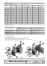
Positioning the first anchoring baffle of the busbars according to the short-circuit current
Anchoring to the switchgear
Fig. 17
Vertical terminals
Circuit-breaker
Iu [A]
Continuous current-
Busbar cross-section
carrying capacity [A]
[mm
2
]
45°C
55°C
E2B 800
800
800
800
1x(60x10)
E2B 1000
1000
1000
1000
1x(80x10)
E2B 1250
1250
1250
1250
1x(80x10)
E2B/N 1600
1600
1600
1600
2x(60x10)
E3N 800
800
800
800
1x(60x10)
E3N 1000
1000
1000
1000
1x(80x10)
E3N 1250
1250
1250
1250
1x(80x10)
E3N/H 1600
1600
1600
1600
2x(60x10)
E3N/H 2000
2000
2000
2000
3x(60x10)
E3N/H 2500
2500
2500
2500
2x(100x10)
E4S 1600
1600
1600
1600
2x(60x10)
E4S 2000
2000
2000
2000
3x(60x10)
E4S 2500
2500
2500
2500
3x(60x10)
E4S/H 3200
3200
3200
3200
3x(100x10)
E6H 3200
3200
3200
3200
3x(100x10)
E6H 4000
4000
4000
4000
4x(100x10)
E6H 5000
5000
5000
4600
6x(100x10)
P
E2
E3-E4-E6
VERTICAL
250
150

