L3447
Emax DC
32/108
L3728
Model
Scale
Page No.
Doc. No.
Apparatus
1SDH000635R0002
12.2.9 Description of the protection functions
12.2.9.1
Protection “L”
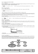
The "L" is the only protection that cannot be disabled because it is for self-protection against overloading of the relay itself. The types of trip curves
settable are divided into two groups according to the IEC standard 60255-8.
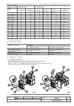
The protection trip time - inverse time - is given by the expression:
where
I
f
is the fault current and
I
1
the protection threshold and with
τ =
t1/ (ln 9/8)
NB: Time expressed in seconds.
12.2.9.1.1 Thermal memory “L”
The thermal memory can be enabled to protect the cables on the basis of the "hot state" tripping curve in IEC 60255-8.
where I
p
is calculated on the basis of the evolution of the current providing there is no overload condition.
The PR122/DC is fitted with two instruments to make up this thermal memory. The first is only effective when the release is powered (it also records
overloads that have not lasted long enough to trip the release), while the second works even when the release is not powered, reducing any trip
times in the case of an immediate reclosing and is enabled as soon as the CB is tripped.
It is the PR122/DC release that automatically decides which of the two to use, according to the various situations.
12.2.9.2
Protection “S”
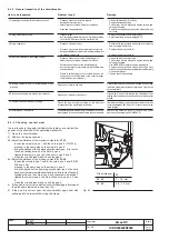
This protection can be disabled; it can be of the fixed time (t=k) or inverse time (t=k/i
2
); in the latter case, the trip time is given by the expression:
where
I
f
>
I
2
where
I
f
is the fault current and
I
2
the protection threshold.
NB: Time expressed in seconds.
12.2.9.2.1 Thermal memory “S”
The thermal memory function can be enabled for cable protection in the case where the curve with inverse time is selected. This is based on the
"tS" parameter defined as the trip time of the curve (t2) selected at 1.5xI2. The other characteristics are the same as those for thermal memory
"L" (see par. 12.2.9.1.1).
12.2.9.2.2 Start-up threshold “S”
The start-up function can be selected in the case where the curve with fixed time is selected.
The function can be disabled and it is a setting characteristic of the single protection units.
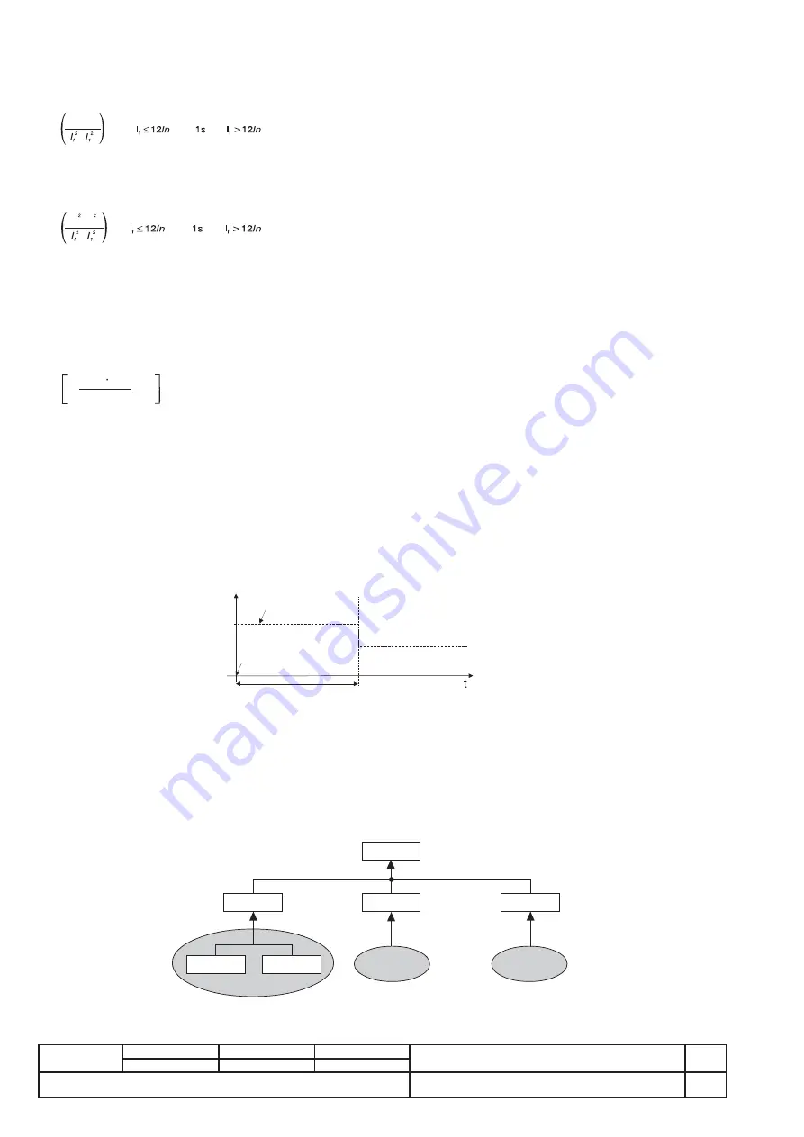
The start-up function enables the protection threshold (S and I) to be changed during a time interval lasting "ts", starting from "start-up". The latter
must be intended as follows:
-
Passage of the RMS value of the maximum current over one single adjustable threshold (0.1…10In, by 0.1In steps). A new start-up is possible
after the current has dropped below this threshold.
• Start-up time
The start-up time is common to all the protections involved. Range: 0.1s … 30s, with steps of 0.01s.
max
100 t
2
(I )
f
2
, t
2
I
t h
Start Up
Start Up
Programmed time
t
s
Threshold I
2
I
f
-
ln
f
or
and
f
or
τ
I
-
ln
I
p
f
-
for
and
for
τ
Area 1
RELAY
1a
RELAY
1b
ZSO
ZSO
1a
1b
RELAY
1
ZSI
1
ZSO
1
Area 2
Area n
○
○
○
○
RELAY
2
ZSI
2
ZSO
2
RELAY
0
ZSI
0
RELAY
n
ZSI
n
ZSO
n
○
○
○
○
12.2.9.2.3 Zone selectivity “S”
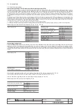
The zone selectivity function, guaranteed only if an auxiliary voltage is provided, enables the area of the fault to be isolated, only isolating the part
of plant nearest to the fault, while keeping the rest of the plant operational.
This is done by connecting all the zone selectivity outputs of the releases belonging to the same zone to one another (ZSO=K51/SZout) and taking
this signal to the zone selectivity input (ZSI=K51/SZin) of the next release on the supply side. If the wiring has been done correctly, all the zone
selectivity inputs of the last circuit-breakers in the chain and all the outputs of the circuit-breakers at the head of each chain must be empty.

