L3447
Emax DC
51/108
Model
Scale
Page No.
Doc. No.
Apparatus
1SDH000635R0002
L3728
13.2.7 Measurement functions
The current measuring (ammeter) function is available on all versions of the SACE PR123/DC unit.
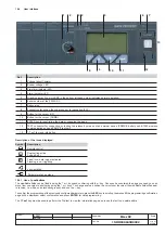
The display shows histogram
s of the polarity
on the main page. In addition, the current of the polarity under the greatest load is given in numerical
form. Where applicable, the earth fault current is displayed on a separate page.
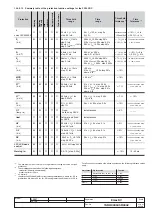
The PR123/DC release provides a complete set of measurements:
- Current
- Voltage
- Instantaneous voltage values over a given time interval (data logger)
- Active power
- Energy
- Maintenance: number of operations, percentage of contact wear, opening data storage.
- Data Logger: see par. 15.2
The PR123/DC can provide the trend of the measurements of certain quantities over an interval P, established by the user; these include: mean
active power, maximum active power, maximum current, maximum voltage and minimum voltage. The last 24 P intervals (adjustable from 5
to 120 min) are stored in a non-volatile memory and displayed in a bar graph.
To examine the Measurement functions, see the relevant paragraphs (par. 14.1 and par. 13.5.3) for the PR120/V-PR120/LV - MEASURING
module.
13.2.8 Watchdog
The PR123/DC unit provides some watchdog functions able to guarantee the proper management of relay malfunctions. These functions are as
follows:
Watchdog for presence of Auxiliary power supply with "plug" icon displayed.
Rating PLUG validity.
Watchdog for proper connection of the trip coil (TC). If it is enabled, any anomalies are indicated by a special alarm message and the "alarm"
LED coming on. If the PR120/D-M module is installed, this activates the coil opening command (YO), thus opening the CB.
Watchdog for protection of Hw Trip. If it is enabled, in the event of CB undefined or a Rating Plug error or an Installation error, a CB opening
command is given by the TC being enabled.
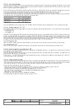
13.2.9 Description of the protection functions
13.2.9.1
Protection “L”
The "L" is the only protection that cannot be disabled because it is for self-protection against overloading of the relay itself.
Only one type of curve can be specified, as defined in the IEC standard 60255-8.
The protection trip time – inverse time - is given by the expression:
τ
where
I
f
is the fault current and
I
1
the protection threshold.
NB: Time expressed in seconds.
13.2.9.1.1 Thermal memory “L”
The thermal memory can be enabled to protect the cables on the basis of the "hot state" tripping curve in IEC 60255-8
where I
p
is calculated on the basis of the evolution of the current providing there is no overload condition
The PR123/DC is fitted with two instruments to make up this thermal memory. The first is only effective when the release is powered (it also records
overloads that have not lasted long enough to trip the release), while the second works even when the release is not powered, reducing any trip
times in the case of an immediate reclosing and is enabled as soon as the CB is tripped.
It is the PR123/DC release that automatically decides which of the two to use, according to the various situations.
13.2.9.2
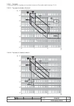
Protection “S”
This protection can be disabled; it can be of the fixed time (t=k) or inverse time (t=k/i
2
) type. In the latter case, the trip time is given by the expression:
13.2.9.2.1 Thermal memory “S”
The thermal memory function can be enabled for cable protection in the case where the curve with inverse time is selected. This is based on the
"tS" parameter defined as the trip time of the curve (t2) selected at 1.5xI2. The other characteristics are the same as those for thermal memory
"L" (see par. 13.2.9.1.1).
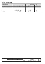
13.2.9.2.2 Start-up threshold “S”
The start-up function can be selected in the case where the curve with fixed time is selected.
The function can be disabled and it is a setting characteristic of the single protection units.
The start-up function enables the protection threshold (S, I and G) to be changed during a time interval lasting "ts", starting from "start-up". The
latter must be intended as follows:
- Passage of the RMS value of the maximum current over one single adjustable threshold (0.1…10In, by 0.1In steps). A new start-up is possible
after the current has dropped below this threshold.
where
I
f
is the fault current and
I
2
the protection threshold.
( )
2
2
2
,
100
max
t
I
t
f
⎥
⎥
⎦
⎤
⎢
⎢
⎣
⎡
⋅
2
I
I
f
>
where
I
f
-
ln
f
or
and
f
or
I
-
ln
I
p
f
-
for
and
for
τ
• Start-up time
The start-up time is common to all the protections involved. Range: 0.1s ... 30s, with steps of 0.01s.
I
t h
Start Up
Start Up
Programmed time
t
s
Threshold I
2

