ADB Safegate SCO, Instruction Manual
The ADB Safegate SCO Instruction Manual is your essential guide to optimizing the performance of our cutting-edge product. Easily download this comprehensive manual for free from our website to access step-by-step instructions, troubleshooting tips, and valuable insights. Maximize your experience with ADB Safegate SCO today! (website)
Share
Download


Reviews:
No comments
Related manuals for SCO

XM2-300HP
Brand: Alpha Pages: 64

AK-2-50
Brand: GE Pages: 47

Sealine Panel 110
Brand: Calira Pages: 4
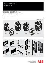
SACE Tmax XT2
Brand: ABB Pages: 5

EntelliGuard AKR30S-800A
Brand: GE Pages: 64

SDV-R
Brand: Siemens Pages: 56

SDV6
Brand: Siemens Pages: 44

UT261B
Brand: UNI-T Pages: 3

h3 HED400G
Brand: hager Pages: 2

H400
Brand: hager Pages: 4

DA-275 DFI 1
Brand: SALTEK Pages: 2

Extech Instruments CT70
Brand: FLIR Pages: 12

BES2 Series
Brand: Schrack Pages: 5

PEBS-S
Brand: Projoy Electric Pages: 2

LW36A-126
Brand: Huayi Pages: 32

LP-900
Brand: Elenco Electronics Pages: 2

LP-600
Brand: Elenco Electronics Pages: 2

LP-500
Brand: Elenco Electronics Pages: 12


