


Section-10
04-3006_S10_TDS_ABB_DPA_UPSCALE_RI_10-80kW_EN_150316.doc
Page 10/16 ABB
Modifications reserved
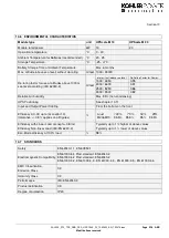
10.8 COMMUNICATION
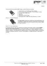
Power Management Display (PMD)
1 LCD display for each module
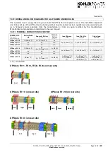
RJ45 Plug (Not used)
RJ45 Plug (for future options)
Customer Interfaces : Outputs
DRY PORT X 2
5 voltage free contacts
For remote signaling and automatic computer shutdown
Customer Interfaces : Inputs
DRY PORT X1
1 x Remote Shut down [EMERGENCY OFF (Normally closed)]
2 x
Programmable Customer’s Inputs
(1
st
default as GEN-ON (Normally open)
(2
nd
free Programmable Cu
stomer’s Inputs (Normally open)
1 x Temp. Sensor for Battery Control
1 x 12 Vdc output (max. 200mA)
Serial ports RS232 on Sub-D9
1 x system frame
For monitoring and integration in network management
USB
1x For monitoring and software management
Slot for SNMP
SNMP card (optional)
For monitoring and integration in network management
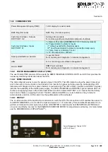
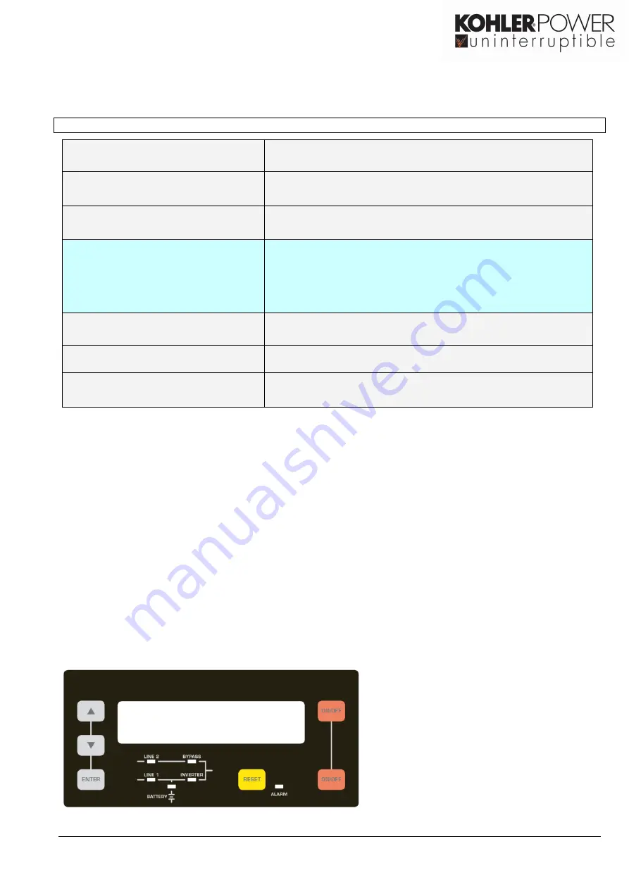
10.8.1 POWER MANAGEMENT DISPLAY (PMD)
The user-friendly PMD consists of three parts the MIMIC DIAGRAM, CONTROL KEYS and LCD that provides the
necessary monitoring information about the UPS.
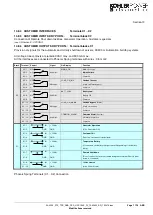
10.8.2 MIMIC DIAGRAM
The mimic diagram serves to give the general status of the UPS. The LED-indicators show the power flow status
and in the event of mains failure or load transfer from inverter to bypass and vice-versa the corresponding LED-
indicators will change color
from green (normal) to red (warning). The LED’s LINE 1 (rectifier) and LINE 2 (bypass)
indicate the availability of the mains power supply. The LED’s INVERTER and BYPASS if green indicate which of
the two are supplying power to the critical load. When the LED-indicator BATTERY is lit it means that the battery
due to mains failure is supplying the load. The LED-indicator ALARM is a visual indication of any internal or
external alarm condition. At the same time the audible alarm will be activated.
10.8.3 DISPLAY
The 2 x 20 character LCD simplifies the communication with the UPS. The menu driven LCD enables the access to
the EVENT REGISTER, or to monitor the input and output U, I, f, P, Autonomy Time and other Measurement’s, to
perform commands like start-up and shut-down of INVERTER or load transfer from INVERTER to BYPASS and
vice-versa and finally it serves for the DIAGNOSIS (SERVICE MODE) for adjustments and testing (for more details
see the USER MANUAL of DPA UPScale
TM
).
Power Management Display (PMD)
of DP
A UPScale™
Summary of Contents for DPA Upscale M 10
Page 27: ......
Page 28: ......
Page 29: ......
Page 31: ......
Page 32: ......
Page 33: ......
Page 35: ......
Page 36: ......
Page 37: ......
Page 39: ......
Page 40: ......
Page 41: ......
Page 43: ......
Page 44: ......
Page 45: ......
Page 47: ......
Page 48: ......
Page 49: ......
Page 51: ......
Page 52: ......
Page 53: ......


