


121
APPENDIX A – CONTROL TEMPLATES…
LSPt
RSPt
M.SPt
M.OP
x
C
.rtO
+
C
.bIA
I/P3
I/P1
I/P2
OP1
Remote Set Point Input
Master Process V
ariable Input
Slave Process V
ariable Input
Slave Set Point
M.PV
Master
PID
Control Loop
•1
•1
T
emplate 12 only
Set Point
Ramp
Manual Output
I/P3 x
rAt0
+
bIAS
MOP
S.PV
S.SPt
Local Set Point
Profile Set Point
M.PV–
M.SPt
S.PV–
S.SPt
L
LR
L
LR
Slave
PID
Control Loop
A5
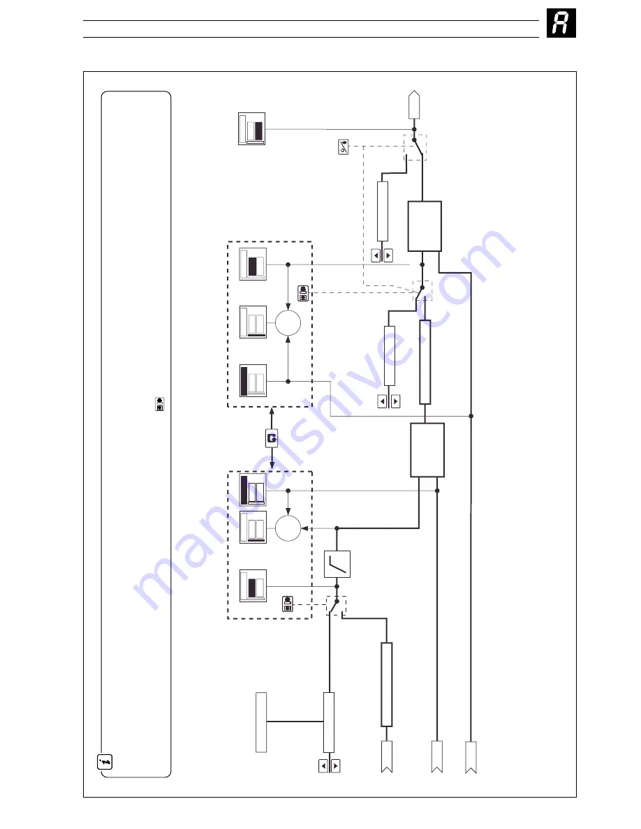
Cascade Controllers (Templates 11 and 12)
Cascade Controller
. Two PID controllers are used with the first (master) controller providing the set point for the second (slave) controller. Th
e two
controllers are linked internally. The master output can be weighted using the cascade ratio (
C
.rto
) and bias (
C
.bia
) values to create the slave set point
value. When the auto/manual mode is changed (from the front panel or by a digital signal) both the master and slave controllers
change mode. In manual
the slave set point can be adjusted by the user and the value is tracked by the master controller to ensure bumpless transfer b
ack into auto. The slave can
also be taken out of cascade mode by selecting local mode using the front panel
L
L
R
key (when slave values are displayed).


