


- 36 -
012C6
6 - System monitoring
L
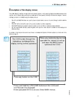
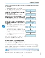
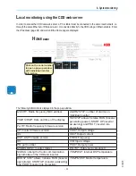
ocal monitoring using the CDD web server
In order to access the CDD local web server, a PC or tablet must be connected to the same local network, i.e.
through the same Ethernet or Wireless router, or connected directly to the CDD using an Ethernet cable. Enter
the IP address (page 24) and wait until the Home page is displayed.
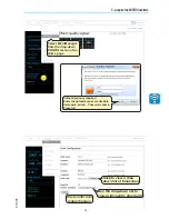
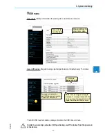
H
OME page
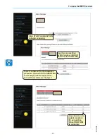
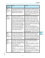
The following information is displayed in the pop-up window:
MAC RF
: Radio frequency MAC address
ALARM STAT:
number of alarms on
individual inverter
TIME STAMP
: Date and time of the display
Fw RF
: Radio frequency firmware version
INV STAT:
allows 3 states, RUN (booster
generating power), START UP (inverter
awakening) and PROT (inverter into
protection)
uP
: inverter firmware version
VOUT:
Output voltage
IDs
:
IOUT:
Output current
DSP
: DSP firmware version
FREQ
: Frequency
IDi
:
VIN
: Input voltage
PN
: part number
POUT
: Output power
MODEL DESC
: inverter model
EN TOT
: Total energy produced
SIGNAL
: strength of radio communication
signal between the CDD and inverter
TEMP DSP
: Internal DSP temperature
BOOST STAT:
allows 3 states, RUN (booster
operational), START UP (booster awakening)
and PROT (booster into protection)
TEMP MOSF
: Mosfet temperature
Click on the serial number
to open a pop-up window
with individual inverter
information