


86 Control unit
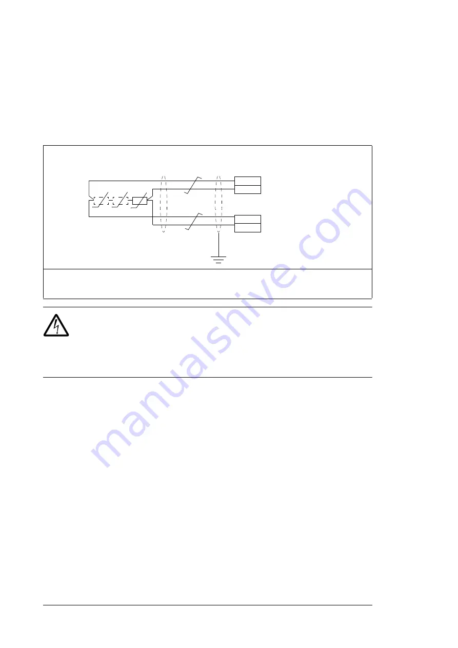
AI1 and AI2 as Pt100, Pt1000, Ni1000, KTY83 and KTY84 sensor inputs
(ANALOG IN/OUT)
One, two or three Pt100 sensors; one, two or three Pt1000 sensors; or one Ni1000, KTY83
or KTY84 sensor for motor temperature measurement can be connected between an
analog input and output as shown below. Do not connect both ends of the cable shields
directly to ground. If a capacitor cannot be used at one end, leave that end of the shield
unconnected.
WARNING!
As the inputs pictured above are not insulated according to
IEC 60664, the connection of the motor temperature sensor requires double or
reinforced insulation between motor live parts and the sensor. If the assembly
does not fulfill the requirement, the I/O board terminals must be protected against contact
and must not be connected to other equipment or the temperature sensor must be isolated
from the I/O terminals.
Safe torque off (STO)
For the drive to start, both connections (+24 V DC to IN1 and +24 V DC to IN2) must be
closed. By default, the terminal block has jumpers to close the circuit.
Remove the jumpers before connecting an external Safe torque off circuitry to the drive.
See also chapter
on page
Note:
Only 24 V DC can be used for STO. Only PNP input configuration can be used.
1. Set the input type to voltage with switch S1 for analog input AI1or with S2 for analog input AI2. Set the
appropriate analog input unit to V (volt) in parameter group
12 Standard AI
.
2. Select the excitation mode in parameter group
13 Standard AO
.
XAI
XAO
AIn
AGND
AOn
AGND
1)
2)
T
T
T
1…3 × (Pt100 or Pt100) or
1 × (Ni1000 or KTY83 or KTY84)
Summary of Contents for ACS580-07-0495A-4
Page 1: ...ABB general purpose drives Hardware manual ACS580 07 drives 250 to 500 kW ...
Page 4: ......
Page 8: ...4 Update notice ...
Page 16: ...12 ...
Page 24: ...20 Safety instructions ...
Page 42: ...38 Operation principle and hardware description ...
Page 74: ...70 Electrical installation PE PE 8 PE 13 11 7 8 12 13 ...
Page 82: ...78 Electrical installation ...
Page 102: ...98 Fault tracing ...
Page 114: ...110 Maintenance R10 and R11 4 5 2 7 6 3 8 ...
Page 115: ...Maintenance 111 R10 and R11 9 10 ...
Page 116: ...112 Maintenance R10 and R11 11 ...
Page 117: ...Maintenance 113 R10 and R11 12b 12a ...
Page 118: ...114 Maintenance R10 and R11 R10 and R11 17 14 13 R11 15 16 ...
Page 134: ...130 Technical data ...
Page 137: ...Dimension drawings 133 13 Dimension drawings Example dimension drawings are shown below ...
Page 138: ...134 Dimension drawings Frames R10 and R11 IP42 ...
Page 139: ...Dimension drawings 135 Frames R10 and R11 IP54 option B055 ...
Page 140: ...136 Dimension drawings ...
Page 152: ...148 Safe torque off function ...
Page 174: ...Contact us www abb com drives www abb com drivespartners 3AXD50000032622 Rev A EN 2016 03 16 ...


