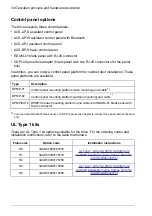
Control panel options
The drive supports these control panels:
• ACS-AP-S assistant control panel
• ACS-AP-W assistant control panel with Bluetooth
• ACS-AP-I assistant control panel
• ACS-BP-S basic control panel
• RDUM-01 blank panel with RJ-45 connector
• CDPI-02 panel bus adapter (blank panel with two RJ-45 connectors for the panel
bus).
In addition, you can order a control panel platform for cabinet door installation. These
panel platforms are available:
Description
Type
Control panel mounting platform (flush mounting) and cable
1)
DPMP-01
Control panel mounting platform (surface mounting) and cable
1)
DPMP-02
DPMP-02 panel mounting platform (and cable) and RDUM-01 blank panel with
RJ-45 connector
DPMP-EXT2
1) You need also RDUM-01 blank panel, or CDPI-02 panel bus adapter to connect the panel cable at the drive
end.
UL Type 1 kits
There are UL Type 1 kit options available for the drive. For the ordering codes and
installation instructions, refer to the table that follows.
Installation instructions
Option code
Frame size
UL Type 1 kit for ACS380, ACS480 and
ACH480 installation guide, frames R0 to R2
3AXD50000187034
R0
3AXD50000176779
R1
3AXD50000178780
R2
UL Type 1 kit for ACS380, ACS480 and
ACH480 installation guide, frames R3 to R4
3AXD50000179220
R3
3AXD50000179336
R4
34 Operation principle and hardware description
Summary of Contents for ACS480-04-09A8-1
Page 1: ... ABB GENERAL PURPOSE DRIVES ACS480 drives Hardware manual ...
Page 2: ......
Page 4: ......
Page 14: ...14 ...
Page 22: ...22 ...
Page 28: ...28 ...
Page 38: ...38 ...
Page 44: ...44 ...
Page 118: ...118 ...
Page 126: ...126 ...
Page 174: ...174 ...
Page 176: ...Frame R0 Frame R0 front side IP20 UL open type 176 Dimension drawings ...
Page 177: ... Frame R0 bottom rear IP20 UL open type Dimension drawings 177 ...
Page 178: ...Frame R1 Frame R1 front side IP20 UL open type 178 Dimension drawings ...
Page 179: ... Frame R1 bottom rear IP20 UL open type Dimension drawings 179 ...
Page 180: ... Frame R1 front side UL Type 1 kit installed 180 Dimension drawings ...
Page 181: ... Frame R1 bottom rear UL Type 1 kit installed Dimension drawings 181 ...
Page 182: ...Frame R2 Frame R2 front side IP20 UL open type 182 Dimension drawings ...
Page 183: ... Frame R2 bottom rear IP20 UL open type Dimension drawings 183 ...
Page 184: ... Frame R2 front side UL Type 1 kit installed 184 Dimension drawings ...
Page 185: ... Frame R2 bottom rear UL Type 1 kit installed Dimension drawings 185 ...
Page 186: ...Frame R3 Frame R3 front side IP20 UL open type 186 Dimension drawings ...
Page 187: ... Frame R3 bottom rear IP20 UL open type Dimension drawings 187 ...
Page 188: ... Frame R3 front side UL Type 1 kit installed 188 Dimension drawings ...
Page 189: ... Frame R3 bottom rear UL Type 1 kit installed Dimension drawings 189 ...
Page 190: ...Frame R4 Frame R4 front side IP20 UL open type 190 Dimension drawings ...
Page 191: ... Frame R4 bottom rear IP20 UL open type Dimension drawings 191 ...
Page 192: ... Frame R4 front side UL Type 1 kit installed 192 Dimension drawings ...
Page 193: ... Frame R4 bottom rear UL Type 1 kit installed Dimension drawings 193 ...
Page 194: ...194 ...
Page 221: ... Declarations of conformity The Safe torque off function 221 ...
Page 231: ...Dimensions BIO 01 I O extension module 231 ...
Page 232: ...232 ...
Page 238: ...Dimensions 3AXD50000031148 rev A 238 BREL 01 relay output extension module ...


