Checking the compatibility of the motor and drive
Use asynchronous AC induction motor, permanent magnet synchronous motor or ABB
synchronous reluctance motor (SynRM motors) with the drive. Multiple induction motors
can be connected to the drive at a time when using the scalar motor control mode.
Make sure that the motor(s) and the drive are compatible according to the rating table
in the technical data.
Selecting the power cables
■
General guidelines
Select the input power and motor cables according to local regulations.
•
Current:
Select a cable capable of carrying the maximum load current and suitable
for the prospective short-circuit provided by the supply network. The method of
installation and ambient temperature affect the cable current carrying capacity. Obey
local regulations and laws.
•
Temperature:
For an IEC installation, select a cable rated for at least 70 °C (158 °F)
maximum permissible temperature of conductor in continuous use.
For North America, select a cable rated for at least 75 °C (167 °F).
Important: For certain product types or option configurations higher temperature rating
may be required. See the technical data for details.
•
Voltage:
600 V AC cable is accepted for up to 500 V AC. 750 V AC cable is accepted
for up to 600 V AC. 1000 V AC cable is accepted for up to 690 V AC.
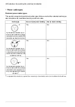
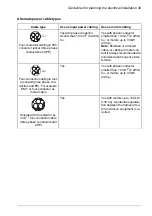
To comply with the EMC requirements of the CE mark, use one of the preferred cable
types. See
Preferred power cable types (page 48)
Symmetrical shielded cable reduces electromagnetic emission of the whole drive system
as well as the stress on motor insulation, bearing currents and wear.
Metal conduit reduces electromagnetic emission of the whole drive system.
■
Typical power cable sizes
See the technical data.
Guidelines for planning the electrical installation 47
Summary of Contents for ACS480-04-09A8-1
Page 1: ... ABB GENERAL PURPOSE DRIVES ACS480 drives Hardware manual ...
Page 2: ......
Page 4: ......
Page 14: ...14 ...
Page 22: ...22 ...
Page 28: ...28 ...
Page 38: ...38 ...
Page 44: ...44 ...
Page 118: ...118 ...
Page 126: ...126 ...
Page 174: ...174 ...
Page 176: ...Frame R0 Frame R0 front side IP20 UL open type 176 Dimension drawings ...
Page 177: ... Frame R0 bottom rear IP20 UL open type Dimension drawings 177 ...
Page 178: ...Frame R1 Frame R1 front side IP20 UL open type 178 Dimension drawings ...
Page 179: ... Frame R1 bottom rear IP20 UL open type Dimension drawings 179 ...
Page 180: ... Frame R1 front side UL Type 1 kit installed 180 Dimension drawings ...
Page 181: ... Frame R1 bottom rear UL Type 1 kit installed Dimension drawings 181 ...
Page 182: ...Frame R2 Frame R2 front side IP20 UL open type 182 Dimension drawings ...
Page 183: ... Frame R2 bottom rear IP20 UL open type Dimension drawings 183 ...
Page 184: ... Frame R2 front side UL Type 1 kit installed 184 Dimension drawings ...
Page 185: ... Frame R2 bottom rear UL Type 1 kit installed Dimension drawings 185 ...
Page 186: ...Frame R3 Frame R3 front side IP20 UL open type 186 Dimension drawings ...
Page 187: ... Frame R3 bottom rear IP20 UL open type Dimension drawings 187 ...
Page 188: ... Frame R3 front side UL Type 1 kit installed 188 Dimension drawings ...
Page 189: ... Frame R3 bottom rear UL Type 1 kit installed Dimension drawings 189 ...
Page 190: ...Frame R4 Frame R4 front side IP20 UL open type 190 Dimension drawings ...
Page 191: ... Frame R4 bottom rear IP20 UL open type Dimension drawings 191 ...
Page 192: ... Frame R4 front side UL Type 1 kit installed 192 Dimension drawings ...
Page 193: ... Frame R4 bottom rear UL Type 1 kit installed Dimension drawings 193 ...
Page 194: ...194 ...
Page 221: ... Declarations of conformity The Safe torque off function 221 ...
Page 231: ...Dimensions BIO 01 I O extension module 231 ...
Page 232: ...232 ...
Page 238: ...Dimensions 3AXD50000031148 rev A 238 BREL 01 relay output extension module ...

