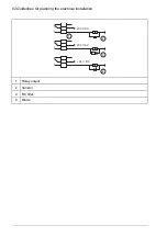
1000 V DC,
>
100 Mohm
U1-PE, V1-PE, W1-PE
ohm
M
3~
U1
V1
W1
PE
■
Measuring the insulation resistance of the brake resistor circuit
WARNING!
Obey the safety instructions of the drive. If you ignore them, injury or death,
or damage to the equipment can occur. If you are not a qualified electrical
professional, do not do installation or maintenance work.
1.
Stop the drive and do the steps in section
Electrical safety precautions (page 18)
before you start the work.
2.
Make sure that the resistor cable is connected to the resistor and disconnected from
the drive output terminals.
3.
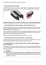
At the drive end, connect the R+ and R- conductors of the resistor cable together.
Measure the insulation resistance between the conductors and the PE conductor
with a measuring voltage of 1000 V DC. The insulation resistance must be more
than 1 Mohm.
R-
R+
ohm
PE
1000 V DC,
> 1 Mohm
Grounding system compatibility check – IEC
This section is applicable to the IEC drive types.
■
EMC filter
The drive has an internal EMC filter as standard. You can install a drive that has the
internal EMC filter connected to a symmetrically grounded TN-S system (center-grounded
Electrical installation – IEC 65
Summary of Contents for ACS480-04-09A8-1
Page 1: ... ABB GENERAL PURPOSE DRIVES ACS480 drives Hardware manual ...
Page 2: ......
Page 4: ......
Page 14: ...14 ...
Page 22: ...22 ...
Page 28: ...28 ...
Page 38: ...38 ...
Page 44: ...44 ...
Page 118: ...118 ...
Page 126: ...126 ...
Page 174: ...174 ...
Page 176: ...Frame R0 Frame R0 front side IP20 UL open type 176 Dimension drawings ...
Page 177: ... Frame R0 bottom rear IP20 UL open type Dimension drawings 177 ...
Page 178: ...Frame R1 Frame R1 front side IP20 UL open type 178 Dimension drawings ...
Page 179: ... Frame R1 bottom rear IP20 UL open type Dimension drawings 179 ...
Page 180: ... Frame R1 front side UL Type 1 kit installed 180 Dimension drawings ...
Page 181: ... Frame R1 bottom rear UL Type 1 kit installed Dimension drawings 181 ...
Page 182: ...Frame R2 Frame R2 front side IP20 UL open type 182 Dimension drawings ...
Page 183: ... Frame R2 bottom rear IP20 UL open type Dimension drawings 183 ...
Page 184: ... Frame R2 front side UL Type 1 kit installed 184 Dimension drawings ...
Page 185: ... Frame R2 bottom rear UL Type 1 kit installed Dimension drawings 185 ...
Page 186: ...Frame R3 Frame R3 front side IP20 UL open type 186 Dimension drawings ...
Page 187: ... Frame R3 bottom rear IP20 UL open type Dimension drawings 187 ...
Page 188: ... Frame R3 front side UL Type 1 kit installed 188 Dimension drawings ...
Page 189: ... Frame R3 bottom rear UL Type 1 kit installed Dimension drawings 189 ...
Page 190: ...Frame R4 Frame R4 front side IP20 UL open type 190 Dimension drawings ...
Page 191: ... Frame R4 bottom rear IP20 UL open type Dimension drawings 191 ...
Page 192: ... Frame R4 front side UL Type 1 kit installed 192 Dimension drawings ...
Page 193: ... Frame R4 bottom rear UL Type 1 kit installed Dimension drawings 193 ...
Page 194: ...194 ...
Page 221: ... Declarations of conformity The Safe torque off function 221 ...
Page 231: ...Dimensions BIO 01 I O extension module 231 ...
Page 232: ...232 ...
Page 238: ...Dimensions 3AXD50000031148 rev A 238 BREL 01 relay output extension module ...


