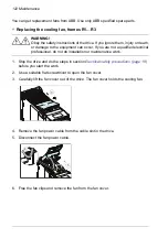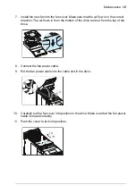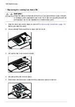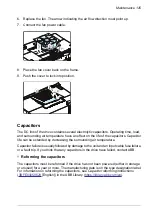
To connect an external auxiliary power supply to the drive:
1.
Install a BAPO-01 power extension module to the drive. See
.
2.
Connect an external power supply to the +24V and DGND terminals of the base
unit.
For more information on the BAPO-01 module, see
BAPO-01 auxiliary power extension
RC
RA
RB
+24
V
DGN
D
DCO
M
SGN
D
S+
DI1
DI2
S1
S2
Connecting a PC
You can connect a PC to the drive. To communicate with the drive, the PC must have
suitable software (for example, Drive composer) installed.
If you have an assistant control panel (ACS-AP-…), use a USB data cable (Type A -
Type Mini-B, maximum length 3 m [9.8 ft]) to connect to the PC. Connect the cable as
follows:
1.
Open the USB connector cover on the control panel.
2.
Connect the USB cable Mini-B plug to the control panel USB connector.
3.
Connect the USB cable A plug to the USB port of the PC. The panel shows text
“USB connected”.
Note:
You cannot use the control panel keys when the drive is connected to a PC.
If you have a RDUM-01 blank panel or CDPI-02 panel bus adapter installed, use a
BCBL-01 USB-RJ45 converter to connect to the PC.
It is also possible to use a CCA-01 configuration adapter when the drive is not connected
to the power supply network or to an external 24 V supply. The CCA-01 does not operate
if the drive is powered.
Installing options
The drive has two option module slots:
• Front option: Communication module slot under the front cover.
Electrical installation – North America 111
Summary of Contents for ACS480-04-09A8-1
Page 1: ... ABB GENERAL PURPOSE DRIVES ACS480 drives Hardware manual ...
Page 2: ......
Page 4: ......
Page 14: ...14 ...
Page 22: ...22 ...
Page 28: ...28 ...
Page 38: ...38 ...
Page 44: ...44 ...
Page 118: ...118 ...
Page 126: ...126 ...
Page 174: ...174 ...
Page 176: ...Frame R0 Frame R0 front side IP20 UL open type 176 Dimension drawings ...
Page 177: ... Frame R0 bottom rear IP20 UL open type Dimension drawings 177 ...
Page 178: ...Frame R1 Frame R1 front side IP20 UL open type 178 Dimension drawings ...
Page 179: ... Frame R1 bottom rear IP20 UL open type Dimension drawings 179 ...
Page 180: ... Frame R1 front side UL Type 1 kit installed 180 Dimension drawings ...
Page 181: ... Frame R1 bottom rear UL Type 1 kit installed Dimension drawings 181 ...
Page 182: ...Frame R2 Frame R2 front side IP20 UL open type 182 Dimension drawings ...
Page 183: ... Frame R2 bottom rear IP20 UL open type Dimension drawings 183 ...
Page 184: ... Frame R2 front side UL Type 1 kit installed 184 Dimension drawings ...
Page 185: ... Frame R2 bottom rear UL Type 1 kit installed Dimension drawings 185 ...
Page 186: ...Frame R3 Frame R3 front side IP20 UL open type 186 Dimension drawings ...
Page 187: ... Frame R3 bottom rear IP20 UL open type Dimension drawings 187 ...
Page 188: ... Frame R3 front side UL Type 1 kit installed 188 Dimension drawings ...
Page 189: ... Frame R3 bottom rear UL Type 1 kit installed Dimension drawings 189 ...
Page 190: ...Frame R4 Frame R4 front side IP20 UL open type 190 Dimension drawings ...
Page 191: ... Frame R4 bottom rear IP20 UL open type Dimension drawings 191 ...
Page 192: ... Frame R4 front side UL Type 1 kit installed 192 Dimension drawings ...
Page 193: ... Frame R4 bottom rear UL Type 1 kit installed Dimension drawings 193 ...
Page 194: ...194 ...
Page 221: ... Declarations of conformity The Safe torque off function 221 ...
Page 231: ...Dimensions BIO 01 I O extension module 231 ...
Page 232: ...232 ...
Page 238: ...Dimensions 3AXD50000031148 rev A 238 BREL 01 relay output extension module ...


