Chapter 3 – Installation Instructions
3-16
ACS 501 Installation & Start-up Manual
Digital (Relay) Outputs
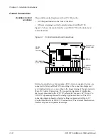
There are three relay outputs which are each Form C. Relay RO1 is on
terminals X50:21, X50:22, and X50:23; Relay RO2 is on terminals X50:24,
X50:25, and X50:26; Relay RO3 is on terminals X50:27, X50:28, and
X50:29.
The first terminal for each relay is the normally closed terminal (NC), the
second is the common, and the third is the normally open (NO).
Maximum Switching Voltage: 300 VDC / 250 VAC
Maximum Switching Current/Power: 8 A @ 24 VDC, 0.4 A @ 250 VDC,
or 2000 VA @ 250 VAC
Maximum Continuous Current: 2 A rms
If the relay outputs are used to control inductive loads, such as the coils of
relays or contactors, some form of noise supression must be provided at the
load. This is to reduce the electrical noise that could interfere with the
electronics in the drive, as well as increase the life of the contacts in the relay.
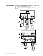
AC coils should be supressed with an MOV (metal oxide varistor) or a Series-
Connected RC (resistor capacitor) network, as illustrated below:
MOV should be rated 120 VAC - 240 VAC for 115 VAC circuits, 240 VAC -
320 VAC for 230 VAC circuits, minimum 10 joules. Values for the RC
Network vary, as they effect the opening and closing time. Contact the
contactor manufacturer for recommended values.
DC coils should be supressed with a diode, although this is not required
because of the small amount of noise generated by these type of circuits. If a
diode is used, it should have a voltage rating greater than or equal to the
supply voltage, and be connected as shown below:
X50
MOV
X50
RC network
115 VAC
115 VAC
X50
diode (24 VDC in this case)
24 VDC
-
+


