


ACS 501 Installation & Start-up Manual
2-1
Chapter 2 – Overview of the ACS 501
This chapter describes the features and functions of the ACS 501, and
includes illustrations and block diagrams. It also describes the ACS 501
hardware components and the Control Panel displays and keys. The last part
of this chapter presents an overview of the Parameters menu system and
Application macros.
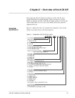
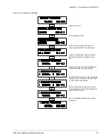
Nameplate
Identification
Figure 2-1 explains the drive code printed on the nameplate, located at the
bottom of your drive between the mounting holes.
Figure 2-1 Explanation of ACS 501 Drive Code
ACS 501 - 002 - 4 - 0 0 P 2
AC = AC Drive
Product Type:
S = Standard Product
Family:
50 = ACS 500
Construction
1 = Sizes 001 to 060, Wall Mounted
2 = Sizes 050 to 300, Std Floor Stand Cabinet
4 = Sizes 050 to 300, Module
Output Power (HP, Constant Torque)
Input Voltage
3 = 380-415 VAC
4 = 440-500 VAC
Internal Option 2
3 = Bus Adapter Card (SNAT 7610 BAC)
Internal Option 1
8 = (5) Isolated Digital Inputs (SNAT 763 DII)
9 = 3-15 PSI and (2) Isolated Digital Inputs (SNAT 762 PSI)
0 = No Option
Control Panel
P = Internal Control Panel (Keypad and Display)
0 = No Panel
Enclosure Type*
0 = Chassis (IP 00)
2 = NEMA 1 (IP 21)
3 = NEMA 1 w/Air Filters
5 = NEMA 12 (IP 54)
6 = NEMA 4 (IP 65)
*Not all Enclosure Types are available for all units.
2 = 208-240 VAC
A = 115 VAC Control Power Board (SNAT 7650 RIB)
Dynamic Braking
Blanks = No Brake
1 = Internal Dynamic Brake Chopper Installed
(KVA, Constant Torque for 380 VAC)
M = MCC Mount
6 = 525-600 VAC


