


Chapter 1 – Introduction
1-2
ACS 501 Installation & Start-up Manual
Intended Audience
The audience for this manual has:
•
Knowledge of standard electrical wiring practices, electronic components,
and electrical schematic symbols.
•
Minimal knowledge of ABB product names and terminology.
•
No experience or training in installing, operating, or servicing the ACS
501.
The audience for this manual will install, start-up, and service the ACS 501.
Conventions Used
In This Manual
Listed below are terms and language conventions used in this manual. These
terms and conventions are defined here to help you understand their meanings
and applications throughout this manual. For a complete listing of ACS 501
terms, refer to the Glossary at the end of this manual.
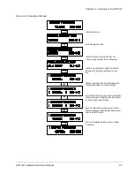
Control Panel Display
The Control Panel display is an LCD readout of drive functions, drive
parameter selections, and other drive information. Letters or numbers appear
in the display according to which Control Panel keys you press.
Control Panel Keys
Control Panel keys are flat, labeled, push-button-type devices that allow you
to monitor drive functions, select drive parameters, and change drive macros
and settings.
Main
A main is the first level of programming. The Mains organize the Parameters
into four main functional groups. A Main in this manual is the number
corresponding to Group access. All Groups in the 10s range are accessed on
the Control Panel through
CONTROL CONNECTIONS/MAIN 10
. Access
Groups in the 20s range through
DRIVE PARAMETERS/MAIN 20
. Access
Groups in the 30s range through
PROTECTION PARAMETER/MAIN 30
,
and access Groups in the 40’s range through
APPLIC PARAMETERS/MAIN
40
.
Group
A Group is a sub-set of a Main. Groups are grouped within Mains according
to their 10s, 20s, 30s, or 40s range. For example, Groups numbered 30.1, 30.2,
30.3, and 30.4 are found in
PROTECTION PARAMETER/MAIN 30
.
Parameters are accessed through Groups.
Parameter
A parameter is a sub-set of a Group, selected through the Control Panel keys.
Parameters in this manual often are expressed as a number, a decimal (.),
another number, a decimal, and another number. The first number at the left
represents the Main. The number between the decimals represents the Group,
for example, 20.2 (Start/Stop). The number at the right represents a Parameter
within that group, for example, 4 (Brake Chopper). In this manual, Parameter
4 in Group 20.2 is expressed as Parameter 20.2.4.
Press
Press a key on the Control Panel to achieve a desired result. In this manual,
individual Control Panel keys are enclosed in square brackets. For example,
the Setting mode key is expressed as [ * ]. Refer to Chapter 2 – Overview of
the ACS 501, Control Panel Operation, for details.


