
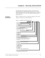


Chapter 3 – Installation Instructions
3-6
ACS 501 Installation & Start-up Manual
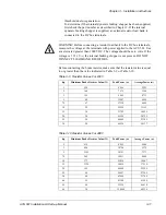
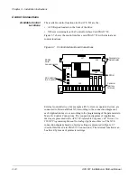
Figure 3-4 shows a bottom view of an ACS 501 R4 drive, and conduit sizes to
fit wire-entry holes.
Figure 3-4
ACS 501 R4 Conduit Sizes
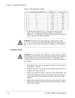
Figure 3-5 shows a bottom view of an ACS 501 R5 drive, and conduit sizes to
fit wire-entry holes.
Figure 3-5
ACS 501 R5 & R5.5 Conduit Sizes
Power Wiring
All field wiring shall be copper conductor rated for 140
°
F (60
°
C) and torqued
to the values in Table 3-4.
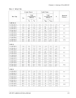
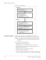
Table 3-4
Wire Torque Values
Table 3-5 indicates the minimum and maximum wire sizes allowable for each
size unit.
Unit
in.-lbs
Nm
R2 & R3
8.8
1
R4, R5 & R5.5
17.6
2
1/2 in.
3/4 in.
1 in.
(25.4 mm)
(19.0 mm)
(12.7 mm)
1/2 in.
3/4 in.
1-1/4 in.
(31.7 mm)
(19.0 mm) (12.7 mm)


