


ACS 501 Installation & Start-up Manual
3-1
Chapter 3 – Installation Instructions
This chapter explains how to install the ACS 501 and connect all power,
motor, and control wiring. It also describes the initial inspection procedures.
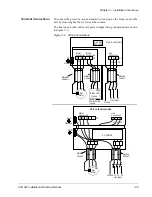
Grounding and
Ground Faults
The ACS 501 must always be grounded through a ground conductor
connected to the ground terminal.
If the ACS 501 is connected to a system without system ground, the ground
fault protection must be capable of starting at ground fault currents containing
high frequency and DC components. The ACS 501 ground fault protection
guards the variable frequency drive against ground faults occurring in the
motor or the motor wiring.
Fault current protective switches do not necessarily operate properly with
variable frequency drives. When using such switches their function should be
checked at possible ground fault currents arising in a fault situation.
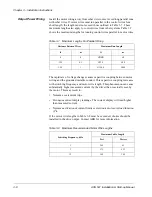
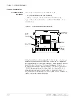
Pre-Installation
Planning
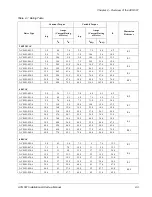
The ACS 500 has been short circuit tested in accordance with UL508.
The R3-R5.5 drives are suitable for use on a circuit capable of delivering not
more than 65,000 rms symmetrical Amperes; R2 unit 20,000 rms symmetrical
Amperes, (240 Volts, 500 Volts or 600 Volts maximum for 230 VAC, 480
VAC, and 600 VAC units respectively).
The drive is supplied with fast acting semiconductor fuses with the following
interrupting capacities.
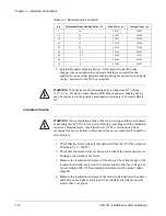
Table 3-1
Fuse Interrupting Capacities
Unit
Capacity
R2
20 kA
R3
100 kA
R4
100 kA
R5
100 kA
R5.5
200 kA


