


Chapter 6 – Service and Maintenance
ACS 501 Installation & Start-up Manual
6-9
Insulation Test
1. Follow Resistance Test Steps 1 – 4, above.
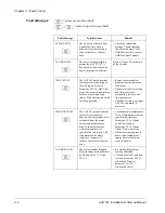
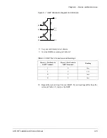
2. Set the insulation tester to the 500 V DC range and test Capacitors C6
and C8 according to Table 6-2.
Table 6-2 Insulation Test Positions and Values
3. Continue with each measurement until the reading stabilizes or until the
reading suddenly falls.
4. If the reading suddenly falls, replace the capacitors. Contact your ABB
Technical Support.
ACS 501 – 007 to 040
Resistance Test
1. Disconnect and lock out power from the ACS 501.
WARNING! Wait at least five minutes after disconnecting power from the
drive before you attempt to service the drive. Bus capacitors in the
intermediate circuit must discharge before servicing the drive. Check for zero
volts at Terminals X50:21 – 29 and X2:(+) and (-) or between the input
terminal block X1 and Terminal Block X2:(+) if an internal brake option is
installed. Failure to check voltage may result in death or serious injury.
2. Check for zero volts at Terminals X50:21 – 29 and X2:(+) and (-) or
between the input terminal block X1 and Terminal Block X2:(+) if an
internal brake option is installed.
CAUTION: Electrostatic Discharge (ESD) can damage electronic circuits.
Do not handle any components without following the proper ESD
precautions.
Note: When disconnecting wires from components and terminals, mark the
wires to correspond to their component and terminal connections.
Drive
Capacitor
Meggar (+) Test Probe
Meggar (-) Test Probe
Reading, V DC
002
C6
Terminal X7
Card edge side of R3
500
C8
Card edge side of R3
Terminal X2:(-)
500
003
C6
Terminal X7
Card edge side of R3
500
C8
Card edge side of R3
Terminal X2:(-)
500
005
C6
Terminal X7
Card edge side of R3
500
C8
Card edge side of R3
Terminal X2:(-)
500


