background image

Chapter 6 – Parameters

ACH 500 Programming Manual

6-37

Group 30.2

Automatic Reset

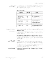
These parameter values can be altered with the ACH 500 running. The Range/
Unit column in Table 6-17 shows parameter values. The text following the 
table explains parameter values in detail.

Table 6-17 Group 30.2

1 NUMBER OF RESETS

Sets the number of resets the ACH 500 will attempt before staying shut down 
and indicating a fault.

2 TIME WINDOW

The maximum number of faults per time period to keep the Automatic Fault 
Reset System active is given with Parameters 30.2.1 (Number of Resets) and 
30.2.2 (Time Window).

If more faults occur or a fault persists longer than Trial Time, the drive stops.

The Automatic Fault Reset System resets the faults selected with Parameters 
30.2.4 (Overvoltage), 30.2.5 (Undervoltage), 30.2.6 (Overcurrent), and 30.2.7 
(AI Signal < Min).

3 TIME BETW.

RESET ATTEMPTS

0 – 120s

This parameter sets the time that the ACH 500 will wait after a fault occurs 
before attempting to reset. If set to zero, the ACH 500 will reset immediately 
making the fault transparent to the user. If set to a value greater than zero, the 
drive will wait before resetting and will count down the time until reset on the 
digital display. For AI Signal < Min Fault, the ACH 500 will start 
immediately when the signal returns.

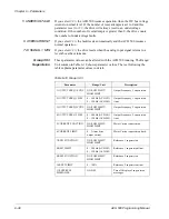
4 OVERVOLTAGE

If you select 

YES

, the ACH 500 resumes operation when the DC bus voltage 

returns to normal level.

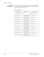
Parameter

Range/Unit

Description

1 NUMBER OF RESETS

0 – 5

Number of faults limit for Autoreset 
logic.

2 TIME WINDOW

1s – 180s

Time limit for Autoreset logic.

3 TIME BETW. RESET 
ATTEMPTS

0s– 120s

Time delay between reset attempts.

4 OVERVOLTAGE

NO/YES

Enable automatic fault reset.

5 UNDERVOLTAGE

NO/YES

Enable automatic fault reset when 
bus voltage returns to normal.

6 OVERCURRENT

NO/YES

Enable automatic fault reset.

7 AI SIGNAL < MIN

NO/YES

Enable automatic fault reset when AI 
is greater than 0.25V.

Summary of Contents for ACH 500

Page 1: ...ACH 500 ABB Drives Programming Manual Including Application Macros ASEA BROWN BOVERI 25 00 U S ACH 500 Adjustable Frequency AC Drives 2 to 400 HP Series B ACH 500 05C EFFECTIVE 11 1 94 SUPERCEDES 6 1 94 ...

Page 2: ... 1994 ABB Drives Inc All Rights Reserved ACH 500 Adjustable Frequency AC Drives 2 to 400 HP Programming Manual Including Application Macros ACH 500 05C EFFECTIVE 1994 11 01 SUPERCEDES 1994 06 01 ...

Page 3: ...conditions which will damage machinery or cause additional motor operation down time if you do not take suggested steps to correct or address such situations or conditions Note Notes provide you with additional and useful information Although less urgent than cautions and warnings notes are important and should not be ignored Warning Symbols For your own safety please pay special attention to inst...

Page 4: ...t the electrical installation Note that the Motor Control Card of the ACH 500 is at DC bus voltage potential The DC bus capacitors contain dangerous DC voltage levels 1 35 x VIN After disconnecting the supply wait at least five minutes after the display readout on the control panel has disappeared before taking any measurements Dangerous external control voltages may be present on the relay output...

Page 5: ...tion 2 3 Chapter 3 Start up Data Start up Data Parameters 3 1 Overview 3 1 Parameter Selection 3 2 Chapter 4 Control Operation Operating Data Parameters 4 1 Overview 4 1 Parameter Selection 4 3 Motor Control Values 4 6 Keypad Control vs External Control 4 7 Keypad Control 4 7 External Control 4 7 Keypad Reference 1 and Keypad PI 4 9 External Reference 1 and 2 4 10 Password Protection Parameter Loc...

Page 6: ...ameters 6 1 Main 10 Control Connections 6 2 Group 10 1 Start Stop Direction 6 2 Group 10 2 Ext Reference Select 6 4 Group 10 3 Preset Speeds 6 7 Group 10 4 System Contr Inputs 6 9 Group 10 5 Analog Inputs 6 10 Group 10 6 Relay Outputs 6 12 Group 10 7 Analog Outputs 6 14 Group 10 8 Ext Communication 6 16 Main 20 Drive Parameters 6 16 Group 20 2 Start Stop 6 17 Group 20 3 Accel Decel 6 20 Group 20 4...

Page 7: ...d describes how to use the menu system of parameters to select and modify the macros Chapter 3 Start up Data lists and explains the Start up Data parameters This chapter also describes how to set the Start up Data parameters Chapter 4 Control Operation describes Operating Data parameters keypad references drive mounted and external controls setting parameters for your specific drive application an...

Page 8: ...ut of drive functions drive parameter selections and other drive information Letters or numbers appear in the display according to which Control Panel keys you press The operation information parameters and fault indications are displayed in nine languages English German Italian Spanish Dutch French Danish Finnish and Swedish The language selection is made in Start up Data Parameter A Language Fig...

Page 9: ...er to the Installation Start up Manual Control Panel Key Text Reference Function Selects the Setting mode and saves the selected parameter value Right Arrow Left Arrow Steps between levels Selects between Operating Data Main Group and Parameter levels and In Setting Mode returns to the Display mode without changing the Parameter value Up Arrow Down Arrow Steps through choices within a level In Dis...

Page 10: ...Chapter 1 Introduction 1 4 ACH 500 Programming Manual This page intentionally left blank ...

Page 11: ... the ACH 500 you can specify a macro as the base setting for a drive You can select any one of the following macros from Start up Data Parameter B Applications HVAC FLOAT PT HVAC PI Pump and Fan In addition to these application macros there is a User macro The User macro allows the user to save the existing parameter settings for recall at a later time Macro programs do not usually set all paramet...

Page 12: ... The Start up Data menu is the first menu you modify to start up your drive 40 2 PUMP FAN CONTROL 40 1 PI CONTROL 30 4 INFORMATION 30 3 SUPERVISION 30 2 AUTOMATIC RESET 30 1 FAULT FUNCTION 20 5 CRITICAL FREQUENCIES 20 4 MOTOR CONTROL 20 3 ACCEL DECEL 20 2 START STOP 20 1 FREQ CURRENT LIMITS 10 8 EXT COMMUNICATION 10 7 ANALOG OUTPUTS 10 6 RELAY OUTPUTS 10 5 ANALOG INPUTS START UP DATA C APPLIC REST...

Page 13: ...exit the Start up Data menu press to confirm the value for the last parameter Parameter K The program returns automatically to Operating Data Parameter 1 Output Frequency Operating Data Parameters The Operating Data menu contains 20 data values status information and three selection functions There are eight additional Operating Data parameters that display when certain applications are selected T...

Page 14: ...sible when you select an Application macro that requires additional set up parameters Figure 2 2 shows how to select the Main level using the Control Panel Keypad Figure 2 2 Main Level Selection START UP DATA C APPLIC RESTORE D Supply Voltage 20 PARAMETER LOCK 30 PROTECTION PARAMETERS 10 CONTROL CONNECTIONS OPERATING DATA MAIN LEVEL 1 OUTPUT FREQ 2 MOTOR SPEED PARAMETERS 20 DRIVE A LANGUAGE APPLIC...

Page 15: ...e Control Panel Keypad Figure 2 3 Group Level Selection 40 2 PUMP FAN CONTROL 40 1 PI CONTROL 30 4 INFORMATION 30 3 SUPERVISION 30 2 AUTOMATIC RESET 30 1 FAULT FUNCTION 20 5 CRITICAL FREQUENCIES 20 4 MOTOR CONTROL 20 3 ACCEL DECEL 20 2 START STOP 20 1 FREQ CURRENT LIMITS 10 8 EXT COMMUNICATION 10 7 ANALOG OUTPUTS 10 6 RELAY OUTPUTS 10 5 ANALOG INPUTS START UP DATA C APPLIC RESTORE D Supply Voltage...

Page 16: ...t the same as those described above Refer to Chapter 3 Start up Data for Start up Data details Figure 2 4 shows how to select a Parameter using the Control Panel Keypad Figure 2 4 Parameter Level Selection 40 2 PUMP FAN CONTROL 40 1 PI CONTROL 30 4 INFORMATION 30 3 SUPERVISION 30 2 AUTOMATIC RESET 30 1 FAULT FUNCTION 20 5 CRITICAL FREQUENCIES 20 4 MOTOR CONTROL 20 3 ACCEL DECEL 20 2 START STOP 20 ...

Page 17: ...required Main Indent to Group level Select the required Indent to Parameter level Select the required Parameter by Up Arrow and Down Arrow key Change to Setting mode Brackets indicate that the parameter value now can be changed Set the parameter value If you want to cancel the change and return to Display mode press Right Arrow or Left Arrow otherwise Save the selected value to parameter memory Br...

Page 18: ...K OPEN xxx START UP DATA START UP DATA A LANGUAGE ENGLISH B APPLICATIONS HVAC C APPLIC RESTORE NO D SUPPLY VOLTAGE 480 230 380 E USER DISPLAY SCALE 0 F MOTOR CURRENT FLA Current Rating G MOTOR POWER Power Rating H MOTOR POWER FACTOR 0 83 10 CONTROL CONNECTIONS 10 1 START STOP DIRECTION 10 1 3 LOC EXT DIRECTION FORWARD 10 3 PRESET SPEEDS 10 3 2 PRESET SPEED 1 5 Hz 10 3 3 PRESET SPEED 2 10 Hz 10 3 4...

Page 19: ...rameter 1 Output Frequency Press and Hold the key while pressing the Right Arrow key This will bring you to Start up Data Parameter A Language The Up Arrow and Down Arrow keys are used to change the value or selection for the Start up Data parameters When a parameter is set to the value or selection you want press the key to enter that value as the acceptable value and move to the next parameter T...

Page 20: ...This parameter is used to set the scaling factor for Operating Data Parameter 2 Speed When set to 0 the speed display will show RPM When set to 100 the speed display will show When set to any other value from 0 10000 the display will show this value minus slip unless slip compensation is ON when the output frequency is at the frequency set by Start up Data Parameter I Motor Base Frequency Paramete...

Page 21: ...the left key for two seconds H MOTOR POWER FACTOR This parameter matches the motor power factor at rated speed and load on sinusoidal power adjustable between 0 10 and 1 0 The drive uses this parameter for motor torque and power information displays I MOTOR BASE FREQUENCY This parameter is used to set the designed frequency of the motor adjustable from 30 Hz to 500 Hz in 10 Hz increments Changing ...

Page 22: ...Chapter 3 Start up Data 3 4 ACH 500 Programming Manual This page intentionally left blank ...

Page 23: ...ot affect drive performance Overview To monitor drive and motor activity select Operating Data Parameters 1 8 These parameters display information about the ACH 500 and motor activity only You cannot change the values of these parameters Refer to Motor Control Values in this chapter for more information on the monitoring functions of Operating Data Parameters 1 8 The Operating Data parameters begi...

Page 24: ...ccuracy 8 DRIVE TEMPERATURE degrees C and F Temperature of the heatsink 9 CONTROL LOCATION KEYPAD R1 KEYPAD PI EXTERNAL Control location selection R1 Referenced PI Closed loop controller 10 KEYPAD REF 1 Hz Frequency reference from Control Panel 11 KEYPAD PI REF 2 Frequency reference controller reference for PI from Control Panel 12 EXT REF 1 OR 2 REF1 REF2 External control place selection 13 EXTER...

Page 25: ...ters 1 OUTPUT FREQUENCY This parameter displays the ACH 500 frequency Hz to the motor Press Up Arrow to move to the next parameter 2 SPEED This parameter displays a calculated speed based on load and slip compensation With no slip compensation motor speed decreases as load increases As default the speed is displayed in motor RPM The scaling of this display is set by Start up Data Parameter E User ...

Page 26: ...switch and speed pot KEYPAD PI to use the Control Panel keypad to change the reference for a PI Controller if using PI control Press to save the setting Press Up Arrow to move to the next parameter 10 KEYPAD REF 1 This parameter displays the ACH 500 reference frequency Hz used when in Keypad R1 Press to enter Setting mode Press Up Arrow or Down Arrow to change the value of the reference frequency ...

Page 27: ...to Chapter 5 Fault Tracing in the Installation Start up Manual for information on resetting faults Press Up Arrow to move to the next parameter 20 PARAMETER LOCK This parameter indicates if the parameters are locked or open If LOCKED or OPEN are followed by xxx then the parameter lock is from the Keypad otherwise the parameter lock is from a digital input The parameter lock allows you to lock all ...

Page 28: ...l number two Displayed in the units set by Parameter 40 2 31 Displ Unit Scale Motor Control Values During motor operation or when troubleshooting you may need to check the vital statistics of the motor and drive Operating Data Parameters 1 8 allow you to view motor and drive activity When controlling the drive from the keypad you may adjust motor speed while displaying Operating Data Parameters 1 ...

Page 29: ...d the Direction and Run indicators on the LCD Display mean Keypad control No square brackets means External control R1 on the LCD means Ref 1 and R2 means Ref 2 Keypad Control When you select KEYPAD R1 or KEYPAD PI from Operating Data Parameter 9 Keypad commands operate the ACH 500 External Control External control locations Ref 1 and Ref 2 are selected with digital inputs 1 6 or Operating Data Pa...

Page 30: ... DI 3 4 5 DI 4 5 6 CRIT FREQUENCIES 20 5 2 20 5 3 CRIT FREQ SELECT 20 5 1 OFF ON ACC DEC TIME 1 20 3 3 20 3 4 ACC DEC TIME 2 20 3 5 20 3 6 ACC DEC RAMP SHAPE 20 3 2 LINEAR S1 SHAPE S2 SHAPE S3 SHAPE ACC DEC 1 OR 2 SEL 20 3 1 EXT1 EXT2 SELECT 10 2 1 OP DATA 12 DI 1 DI 2 DI 3 DI 4 DI 5 DI 6 NO SEL DI 1 DI 6 MINIMUM FREQUENCY 20 1 1 MAXIMUM FREQUENCY 20 1 2 0 500 Hz ACH 501 REF CONTROLS DIRECTION 10 ...

Page 31: ...tion is changed to Keypad R1 it is possible to let the Keypad Ref 1 assume the current value of the External Reference Example The ACH 500 is receiving frequency reference from a transducer via Terminal Block X50 You want to temporarily override the external frequency reference 1 Set Operating Data Parameter 9 Control Location to KEYPAD R1 2 Press and hold down Start Stop and press Note If externa...

Page 32: ...meter Lock or Parameter 10 4 3 Param Lock Sel Keypad DI1 DI6 it is not possible to select the Setting mode to change any ACH 500 parameters but all parameters may be accessed and viewed The ACH 500 Parameter Lock can be controlled with Keypad Operating Data Parameter 23 Parameter Lock or a digital input The control location is selected with Parameter 10 4 3 Param Lock Sel Keypad DI1 DI6 To activat...

Page 33: ...ter Settings User Macro The User macro allows the current parameter settings to be stored in memory To store your customized parameters 1 Access the Start up Data menu 2 Change Parameter B Application to USER save 3 Press to save 4 Press for each of the remaining Start up Data Parameters to get back to the Operating Data The current settings are now stored in the User macro Changes can be made to ...

Page 34: ...c pressure Speed increase and speed decrease contacts FLOAT PT HVAC PI Intended for use with different closed loop control systems such as pressure control level control and flow control For example Booster pumps of municipal water supply systems Automatic level control of water reservoirs Booster pumps of district heating systems Supply or return fans of HVAC system Process HVAC PI Pump and Fan C...

Page 35: ...ay contact signals are available on Terminal Block X50 Operation Diagram Figure 5 1 Operation Diagram Input and Output Signals Table 5 2 Input and Output Signals Input Signals Output Signals Two Analog Reference inputs Six Digital Inputs Start Hand Start Auto Preset Speed 2 Auto Select and Run Enable Analog Output AO1 Output Frequency Analog Output AO2 Output Current Relay Output RO1 READY Relay O...

Page 36: ...nce Hand Reference Auxiliary voltage output 24 V DC 200mA 24 V max 10 mA START HAND AUTO SELECT PRESET SPEED SELECT RUN ENABLE START AUTO Output Frequency Output Current READY FAULT A f Ready Run Select voltage or current reference with plugs Fault 120V AC S1 and S2 on the customer interface board beside the screw terminals 1 6 of X50 Operation D15 D16 Output 0 1 0 1 0 0 1 1 set freq through AI1 P...

Page 37: ...UENCY RANGE 0 120 Hz 20 1 4 CURRENT LIMIT 1 1 x INSQ 20 2 START STOP 20 2 1 START FUNCTION FLYING 20 2 2 TORQUE BOOST CURR 1 5 x IN 20 2 3 STOP FUNCTION COAST 20 2 4 BRAKE CHOPPER NO 20 2 5 DC HOLD OFF 20 2 6 DC HOLD VOLTAGE 0 01 x VN 20 2 7 DC BRAKE VOLTAGE 0 01 x VN 20 2 8 DC BRAKE TIME 0s 20 3 ACCEL DECEL 20 3 1 ACC DEC 1 0R 2 SEL NOT SEL 20 3 2 ACC DEC RAMP SHAPE LINEAR 20 3 3 ACCEL TIME 1 30s...

Page 38: ...eed of the ACS 500 Operation Diagram Figure 5 3 Operation Diagram Input and Output Signals Table 5 3 Input and Output Signals Input Signals Output Signals Two Analog Reference inputs Six Digital Inputs Start Hand Start Auto Preset Speed 2 Auto Select and Run Enable Analog Output AO1 Output Frequency Analog Output AO2 Output Current Relay Output RO1 READY Relay Output RO2 RUN Relay Output RO3 FAULT...

Page 39: ... RO 23 RO 31 RO 32 RO 33 Function Reference voltage 10 VDC 10 mA Auto Reference Hand Reference Auxiliary voltage output 24 V DC 200mA 24 V max 10 mA START HAND AUTO SELECT ACCEL RUN ENABLE START AUTO Output Frequency Output Current READY FAULT A f Ready Run Select voltage or current reference with plugs Fault 120V AC S1 and S2 on the customer interface board beside the screw terminals 1 6 of X50 D...

Page 40: ...1 3 FREQUENCY RANGE 0 120 Hz 20 1 4 CURRENT LIMIT 1 1 x INSQ 20 2 START STOP 20 2 1 START FUNCTION FLYING 20 2 2 TORQUE BOOST CURR 1 5 x IN 20 2 3 STOP FUNCTION COAST 20 2 4 BRAKE CHOPPER NO 20 2 5 DC HOLD OFF 20 2 6 DC HOLD VOLTAGE 0 01 x VN 20 2 7 DC BRAKE VOLTAGE 0 01 x VN 20 2 8 DC BRAKE TIME 0s 20 3 ACCEL DECEL 20 3 1 ACC DEC 1 0R 2 SEL NOT SEL 20 3 2 ACC DEC RAMP SHAPE LINEAR 20 3 3 ACCEL TI...

Page 41: ...e signal and Place B is intended for closed loop speed control using the same reference as Place A Preset speed overrides external analog settings Operation Diagram Figure 5 5 Operation Diagram Input and Output Signals Table 5 4 Input and Output Signals Input Signals Output Signals Two Analog Reference inputs Six Digital Inputs Start Hand Start Auto Preset Speed 2 Auto Select and Run Enable Analog...

Page 42: ...A Actual 1 Hand Reference and Auxiliary voltage output 24 V DC 200mA 24 V max 10 mA START HAND AUTO SELECT PRESET SPEED SELECT RUN ENABLE START AUTO Output Frequency Output Current READY FAULT A f Ready Run Select voltage or current reference with plugs Fault 120V AC S1 and S2 on the customer interface board beside the screw terminals 1 6 of X50 Operation D15 D16 Output 0 1 0 1 0 0 1 1 set freq th...

Page 43: ... 20 2 6 DC HOLD VOLTAGE 0 01 x VN 20 2 7 DC BRAKE VOLTAGE 0 01 x VN 20 2 8 DC BRAKE TIME 0s 20 3 ACCEL DECEL 20 3 1 ACC DEC 1 0R 2 SEL NOT SEL 20 3 2 ACC DEC RAMP SHAPE LINEAR 20 3 3 ACCEL TIME 1 30s 20 3 4 DECEL TIME 1 30s 20 3 7 ACCEL REF2 TIME 0 1s 20 3 8 DECEL REF2 TIME 0 1s 20 4 MOTOR CONTROL 20 4 1 SWITCHING FREQ 3 kHz 20 4 2 MAX OUTPUT VOLTAGE 460 V 20 4 3 V HZ RATIO SQUARED 20 4 4 FIELD WE...

Page 44: ...atical operations addition subtraction multiplication minimum maximum and square root to get a correct final actual value for the PI controller The PI controller can also be bypassed and actual value used as the speed reference Operation Diagram Figure 5 7 Operation Diagram Input and Output Signals Table 5 5 Input and Output Signals Input Signals Output Signals Actual value 4 20 mA Analog Output A...

Page 45: ...AUTO Output Frequency Motor Current Relay Output 1 FAULT A f Select voltage or current reference with plugs S1 and S2 on the customer interface board beside the screw terminals 1 6 of X50 Open switch Manual direct speed setting Terminal X50 1 2 3 4 5 6 8V Power to Remote Panel RS485 Serial Link Connections GND2 Shield1 GND3 SGNA SGNB 7 Shield2 Transducer Feedback B Manual Speed Reference PT 10 mA ...

Page 46: ...s 20 3 4 DECEL TIME 1 1s 20 3 5 ACCEL TIME 2 60s 20 3 6 DECEL TIME 2 60s 20 3 7 ACCEL REF2 TIME 0 1s 20 3 8 DECEL REF2 TIME 0 1s 20 4 MOTOR CONTROL 20 4 1 SWITCHING FREQ 3 kHz 20 4 2 MAX OUTPUT VOLTAGE 100 X VN 20 4 3 V HZ RATIO LINEAR 20 4 4 FIELD WEAK POINT 60 Hz 20 4 5 IR COMPENSATION NO 20 4 6 IR COMP VOLTAGE 0 01 x VN 20 4 7 IR COMP RANGE 0 Hz 20 4 8 SLIP COMPENSATION OFF 20 4 9 NOMINAL SLIP ...

Page 47: ...TROL 30 4 INFORMATION 30 3 SUPERVISION 30 2 AUTOMATIC RESET 30 1 FAULT FUNCTION 20 5 CRITICAL FREQUENCIES 20 4 MOTOR CONTROL 20 3 ACCEL DECEL 20 2 START STOP 20 1 FREQ CURRENT LIMITS 10 8 EXT COMMUNICATION 10 7 ANALOG OUTPUTS 10 6 RELAY OUTPUTS 10 5 ANALOG INPUTS START UP DATA C APPLIC RESTORE D Supply Voltage 20 PARAMETER LOCK 30 PROTECTION PARAMETERS 10 CONTROL CONNECTIONS 10 4 SYSTEM CONTR INPU...

Page 48: ... connected to DI1 and Reverse to DI2 0 V DC on DI2 Forward and 24 V DC Reverse DI1P 2P Three wire start stop Start Stop commands are from momentary push buttons The stop push button is normally closed and connected to DI2 The start push button is normally open and connected to DI1 Multiple start push buttons are connected in parallel and stop push buttons in series DI1P 2P 3 Three wire start stop ...

Page 49: ...art Stop is connected to DI6 and Reverse is connected to DI5 0 V DC on DI5 Forward KEYPAD Start Stop command and Direction command are from the Keypad for Ext 1 2 EXT 2 STRT STP DIR This parameter selects the Digital Inputs used for Start Stop and Reverse commands The choices are the same as Parameter 10 1 1 Ext 1 Strt Stp Dir 3 DIRECTION This parameter allows you to fix rotation direction to FORW...

Page 50: ...eference from analog input 1 AI2 Reference from analog input 2 Parameter Range Unit Description 1 EXT 1 EXT 2 SELECT O OP DATA 12 DI1 DI6 External control location selection input 2 EXTERNAL REF1 SEL O OP DATA 13 Analog and Digital Inputs External reference 1 input 3 EXT REF1 MINIMUM 0 500 Hz ACS 501 0 120 Hz ACS 502 External reference 1 minimum value 4 EXT REF1 MAXIMUM 0 500 Hz ACS 501 0 120 Hz A...

Page 51: ...ure 6 2 shows Joystick control Figure 6 2 Joystick Control DI3U 4D R Speed reference via digital inputs as Floating Point Control or Motor Operated Potentiometer Control DI3 increases speed and DI4 decreases speed R indicates that the reference will reset to minimum frequency when stop command is given The rate of change of the reference signal is controlled by parameter 20 3 5 ACCEL TIME 2 DI3U 4...

Page 52: ... sources AI1 AI2 and AI1 JOYST Example The reference is 20 Hz EXT REF1 OFFSET is 5Hz and EXT REF1 GAIN is 10 The drive reference is now 20Hz 5Hz 0 1 20Hz 27Hz 7 EXTERNAL REF2 SEL OP DATA 14 This parameter selects the signal source for External Reference 2 Reference is given from the Keypad Operating Data Parameter 14 AI1 Reference from analog input 1 AI2 Reference from analog input 2 DI3U 4D R Spe...

Page 53: ...rride any other reference Preset speeds are activated with Digital Input s selected through Parameter 10 3 1 Preset Speed Sel Note Parameter 10 3 8 Preset Speed 7 is a fault frequency which may be activated in case of a serial communication fault or a loss of analog input fault Refer to Parameter 30 1 1 Serial Fault Func and 30 1 2 AI Min Func when in external mode Parameter Range Unit Description...

Page 54: ...Preset Speeds 1 3 are selected with two Digital Inputs as in DI1 2 DI5 6 Three Preset Speeds 1 3 are selected with two Digital Inputs as in DI1 2 DI1 2 3 Seven Preset Speeds 1 7 are selected with three Digital Inputs Table 6 5 Digital Inputs DI1 2 3 DI3 4 5 Refer to DI1 2 3 DI1 DI2 Function 0 0 No Preset Speed 1 0 Preset Speed 1 0 1 Preset Speed 2 1 1 Preset Speed 3 DI1 DI2 DI3 Function 0 0 0 No P...

Page 55: ...keypad Reset is activated by opening a normally closed contact negative edge on digital input If ON STOP is selected a fault is reset by giving a stop command from the active STOP signal or from the Keypad 3 PARAM LOCK SEL This parameter selects the control location for Parameter Lock If you select OP DATA 20 Parameter Lock is controlled with Operating Data Parameter 20 Parameter Lock If you selec...

Page 56: ... must be greater than 0 3 V 0 6 mA When the minimum is set less than this level the between the volts and milliamps will disappear indicating the living zero is not active even if it has been programmed 2 MAXIMUM AI1 10V 20mA READ INPUT When the maximum reference is less than 10 V or 20 mA this parameter will set what the maximum reference is so the drive will run at full speed when this reference...

Page 57: ...e 0 01s the signal is not filtered Figure 6 3 shows filter time constant Figure 6 3 Filter Time Constant 4 INVERT AI1 NO YES If this parameter is set to YES maximum reference gives minimum frequency and minimum reference gives maximum frequency 5 MINIMUM AI2 Refer to Parameter 10 5 1 6 MAXIMUM AI2 Refer to Parameter 10 5 2 7 RC FILTER ON AI2 Refer to Parameter 10 5 3 8 INVERT AI2 Refer to Paramete...

Page 58: ...up Manual for more details FAULT 1 Relay energizes when power is applied and de energizes upon a fault trip FAULT RST The ACS 500 is in a fault condition but will reset after the programmed autoreset delay STALL FLT Stall protection has tripped MOT OT FLT Motor overload I2t protection has tripped OT FAULT The ACS 500 overheat protection has tripped The tripping level is 158 F 70 C for ACS 501 and ...

Page 59: ...Limit REF 1 LIMIT Reference 1 has exceeded the set Supervision Limit Refer to Parameter 30 3 8 Ref 1 Limit REF 2 LIMIT Reference 2 has exceeded the set Supervision Limit Refer to Parameter 30 3 10 Ref 2 Limit AT SPEED The output frequency is equal to the set frequency 25 Hz of set frequency HIGH TEMP High heatsink temperature indication with hysteresis Relay activates at 60 C 140 F and opens at 40...

Page 60: ... Hz OUT CURR Output current 20 mA motor nominal current MOT TORQ Motor torque 20 mA 100 of motor nominal rating MOT POWER Motor power 20 mA 100 of motor nominal rating Parameter Range Unit Description 1 ANALOG OUTPUT 1 O Refer to the text below for the available selections Analog Output 1 content 2 SCALE AO1 10 1000 Analog Output signal 1 scaling factor 3 MINIMUM AO1 0 mA 4 mA Analog Output signal...

Page 61: ... If you select 100 the nominal value of the output signal corresponds to 20 mA If the maximum is less than full scale increase the value of this parameter 3 MINIMUM AO1 The minimum value of the Analog Output signal can be set to either 0 mA or 4 mA 4 RC FILTER ON AO1 Filter time constant for Analog Output 1 As Analog Output value changes 63 percent of the change takes place within the time period ...

Page 62: ...esents the minimum output frequency 2 MAXIMUM FREQUENCY Represents the maximum output frequency 3 FREQUENCY RANGE To use the ACH 501 for frequencies higher than 120 Hz you must first change this parameter This parameter sets the range for all frequency parameters 0 120 Hz Default frequency range Output frequency display to 0 01 Hz 0 500 Hz Extended frequency range Available for ACH 501 only Output...

Page 63: ... is already rotating such as in a fan drive The drive will start smoothly at the current frequency instead of starting at 0 Hz Note Flying Start searches for the running speed by applying a small voltage to the load at the maximum frequency and decreasing the output frequency until the load speed is found If the motor is not coupled to a load or the load has low inertia the shaft speed can follow ...

Page 64: ...ps 0 5 2 0 x IN 1 step 3 STOP FUNCTION COAST The ACH 500 AC drive stops supplying voltage immediately after stop command is received and the motor coasts to a stop RAMP Ramp deceleration as set in Group 20 3 DC BRAKE DC injection braking stops the motor by applying DC to the stator windings By using DC braking the motor can be stopped in the shortest possible time outside of using a dynamic brakin...

Page 65: ...tilated motors should be used In a long DC Hold period the DC Hold cannot keep the motor shaft from rotating if a constant load is applied to the motor 6 DC HOLD VOLTAGE Sets the voltage level applied to the motor when DC Hold is activated Range is from 0 01 to 0 1 times the nominal voltage 7 DC BRAKE VOLTAGE When the stop function is set to DC BRAKE this parameter sets the voltage injected into t...

Page 66: ...eceleration and or slow ramps S1 SHAPE Suitable for ramp times less than one second S2 SHAPE Suitable for ramp times less than 1 5 seconds S3 SHAPE Suitable for ramp times up to 15 seconds Figure 6 5 shows acceleration and deceleration ramp shapes Parameter Range Unit Description 1 ACC DEC 1OR2 SEL O Not Sel DI1 DI6 Acceleration Deceleration ramp selection 2 ACC DEC RAMP SHAPE Linear S1 S3 Accel D...

Page 67: ...t Limit Conversely if a small number is entered for deceleration time in such a system the deceleration time will be limited by the DC bus regulator In some cases the motor will take a long time to come to a stop If a short deceleration time is critical to your application we suggest you add a dynamic braking device to your system The maximum minimum recommended acceleration deceleration for the n...

Page 68: ...arameter Range Unit Description 1 SWITCHING FREQ 1 0 12 0 kHz ACH 501 3 0 kHz ACH 502 Carrier frequency selection 2 MAX OUT VOLTAGE 0 15 1 05 times drive output voltage Maximum motor voltage selection 3 V Hz RATIO LINEAR SQUARED AUTOMATIC Voltage to frequency relationship in region below Field Weakening Point 4 FIELD WEAK POINT 30 500 Hz Threshold for nominal voltage 5 IR COMPENSATION NO MANUAL AU...

Page 69: ...ning point This parameter is automatically set to the same value as Start up Data Parameter K Motor Nom Voltage when that parameter is changed Set in actual volts step equals 1 of VN Range is 0 15 1 05 x VN 3 V Hz RATIO LINEAR The voltage of the motor changes linearly with frequency in the constant torque area Linear V Hz ratio is normally used in Torque control mode or where the torque characteri...

Page 70: ...is set to SQUARED or AUTOMATIC Parameter 20 4 5 IR Compensation must be set to NO 4 FIELD WEAK POINT The Field Weakening Point is the frequency where the output voltage reaches the maximum output voltage Above this frequency the voltage remains at the maximum motor voltage value Figure 6 7 shows various field weakening points Figure 6 7 Field Weakening Points Figure 6 8 shows Parameters 20 4 2 and...

Page 71: ...ser sets the compensation voltage and range Parameters 20 4 6 and 20 4 7 AUTOMATIC The IR Compensation voltage is automatically controlled as a function of effective motor current This setting is suitable when the need for IR Compensation changes or manual optimization of the compensation voltage is difficult Figure 6 9 shows IR Compensation applying extra voltage to a motor Figure 6 9 IR Compensa...

Page 72: ...z 7 IR COMP RANGE This parameter defines the frequency at which the Manual IR Compensation reduces to zero The compensation voltage reduces linearly when the frequency increases If Start Up Data Parameter I Motor Base Frequency or Parameter 20 4 4 Field Weak Point is changed to a value lower than Parameter 20 4 7 IR Comp Range that value will automatically be copied to Parameter 20 4 7 IR Comp Ran...

Page 73: ...utput frequency if the DC bus voltage exceeds the high DC bus voltage limit level typically from an overhauling load to prevent an overvoltage trip The undervoltage controller will decrease the output frequency if the DC bus voltage drops below the low DC bus voltage limit caused by a loss of input power By decreasing the output frequency the inertia of the load will cause regeneration back into t...

Page 74: ...500 Hz ACH 501 0 120 Hz ACH 502 Critical frequency 1 end 4 CRIT FREQ 2 LOW 0 500 Hz ACH 501 0 120 Hz ACH 502 Critical frequency 2 start 5 CRIT FREQ 2 HIGH 0 500 Hz ACH 501 0 120 Hz ACH 502 Critical frequency 2 end 6 CRIT FREQ 3 LOW 0 500 Hz ACH 501 0 120 Hz ACH 502 Critical frequency 3 start 7 CRIT FREQ 3 HIGH 0 500 Hz ACH 501 0 120 Hz ACH 502 Critical frequency 3 end 8 CRIT FREQ 4 LOW 0 500 Hz AC...

Page 75: ...ivate the Critical Frequency settings select Parameter 20 5 1 Crit Freq Select YES Note Set unused Critical Frequencies to 0 Hz Example Fan system with bad vibration from 18 Hz to 23 Hz and from 46 Hz to 52 Hz Running speed set to 60 Hz with reference Set the parameters as follows 2 CRIT FREQ 1 LOW 18 Hz 3 CRIT FREQ 1 HIGH 23 Hz 4 CRIT FREQ 2 LOW 46 Hz 5 CRIT FREQ 2 HIGH 52 Hz If due to bearing we...

Page 76: ...rial Communication fault 2 AI MIN FUNCTION NO WARNING FAULT PRE SPEED7 LAST SPEED Operation in case of AI Minimum fault 3 MOT TEMP FLT FUNC NO WARNING FAULT Operation in case of motor overtemp 4 MOTOR THERM TIME 20 10000s Time for 63 temperature rise 5 MOTOR LOAD CURVE 50 150 Motor current maximum limit 6 ZERO SPEED LOAD 40 MOTOR LOAD CURVE Motor load curve point at zero speed 7 BREAK POINT 1 Hz 5...

Page 77: ...ut frequency goes to the value set by Parameter 10 3 8 Preset Speed 7 LAST SPEED Fault indication on display and the output frequency goes to the last speed average over the last 10 seconds 3 MOT TEMP FLT FUNC This parameter defines the operation of the motor thermal protection function NO No activity wanted WARNING Warning indication is displayed when the motor temperature reaches the warning lev...

Page 78: ...me Motor Therm Time is the time period within which the motor temperature reaches 63 percent of the final temperature rise As a rule of thumb Motor Thermal Time equals 35 times t6 t6 in seconds is the safe operating time at locked rotor current given by the motor manufacturer Because of the simple thermal model used for calculating temperature rise this technique of thermal protection may cause un...

Page 79: ... to 700s which is the value for a Class 20 trip curve This has been tested and is UL Listed as motor overload protection The time for a Class 10 trip curve is 350s and for a Class 30 trip curve is 1050s Table 6 16 Motor Thermal Times PN HP Number of Poles 2 4 6 t s t s t s 3 660 1020 1440 5 780 1140 1740 7 5 900 1260 1760 10 970 1380 1860 15 1140 1560 2040 20 1200 1740 2340 25 1260 1860 2340 30 13...

Page 80: ...llustration of the Motor Load Curve The current is adjustable from 40 to the Motor Load Curve set by Parameter 30 1 5 Motor Load Curve 7 BREAK POINT This parameter defines the point at which the motor load curve begins to decrease from the maximum value set by Parameter 30 1 5 Motor Load Curve to the Zero Speed Load Parameter 30 1 6 The value is adjustable from 1 Hz to 500 Hz Refer to Figure 6 12 ...

Page 81: ...10s 15Hz 20s 25Hz 30s 35Hz This parameter sets the time and frequency values for the stall function 11 UNDERLOAD FUNC Removal of motor load may indicate a process malfunction The protection is activated if The motor torque drops below the load curve selected in Parameter 30 1 13 Underload Curve This condition has lasted longer than the time set in Parameter 30 1 12 Underload Time and Output freque...

Page 82: ...c Figure 6 16 shows five available Underload Curve types If the load drops below the set curve for a longer time than the time set by Parameter 30 1 12 the underload protection will activate Curves 1 3 reach maximum at the Field Weakening Point set by Parameter 20 4 4 Field Weak Point Figure 6 16 Underload Curve Types Underload Curve T M 5Hz ƒ Underload Region ƒ of 100 80 60 40 20 0 120 Hz ƒ Hz 3 ...

Page 83: ...W RESET ATTEMPTS 0 120s This parameter sets the time that the ACH 500 will wait after a fault occurs before attempting to reset If set to zero the ACH 500 will reset immediately making the fault transparent to the user If set to a value greater than zero the drive will wait before resetting and will count down the time until reset on the digital display For AI Signal Min Fault the ACH 500 will sta...

Page 84: ...ows parameter values The text following the table explains parameter values in detail Table 6 18 Group 30 3 Parameter Range Unit Description 1 OUTPUT FREQ 1 FUNC NO LOW LIMIT HIGH LIMIT Output Frequency 1 supervision 2 OUTPUT FREQ 1 LIM 0 500 Hz ACH 501 0 120 Hz ACH 502 Output Frequency 1 supervision limit 3 OUTPUT FREQ 2 FUNC NO LOW LIMIT HIGH LIMIT Output Frequency 2 supervision 4 OUTPUT FREQ 2 ...

Page 85: ...le from 0 500 Hz ACH 501 or 0 120 Hz ACH 502 0 1 Hz step 3 OUTPUT FREQ 2 FUNC Refer to Parameter 30 3 1 4 OUTPUT FREQ 2 LIMIT A second output frequency supervision limit adjustable from 0 500 Hz ACH 501 or 0 120 Hz ACH 502 0 1 Hz step 5 CURRENT FUNCTION Motor Current supervision Operates the same as Parameter 30 3 1 6 CURRENT LIMIT Motor current supervision limit Setting in actual amps step is 1 o...

Page 86: ...eter values The text following the table explains parameter values in detail The parameters in this group show the status of the I O Table 6 20 Group 30 5 Parameter Range Unit Description 1 CRI PROG VERSION CRHxxy Control Interface Card program version 2 MC PROG VERSION MCRxxy CNTxxy Motor Control Card program version 3 TEST DATE YY MM DD Test date year month day Parameter Range Unit Description 1...

Page 87: ...ange is 3 800 If you select 100 a 10 change in error value causes controller output to change by 1 5 Hz Parameter Range Unit Description 1 PI CONT GAIN 3 800 PI Controller Gain selection 2 PI CONT I TIME 0 02 320 00s PI Controller I time selection 3 PI CONT MIN LIMIT 0 120 Hz PI Controller output freq minimum limit 4 PI CONT MAX LIMIT 0 120 Hz PI Controller output freq maximum limit 5 ERROR VALUE ...

Page 88: ...ue of the PI Controller frequency output The limit cannot be set greater than 20 1 2 Maximum Frequency Range is 0 120 Hz 0 01 Hz Step 5 ERROR VALUE INVERT This parameter allows you to invert the Error Value and thus the operation of the PI Controller Normally a decrease in Actual Signal Feedback causes an increase in drive speed If a decrease in Actual should cause a decrease in speed set Error Va...

Page 89: ...to 1600 0 The minimum Actual Value corresponds to the minimum scaled Actual Value 100 The maximum Actual Value corresponds to the minimum scaled Actual Value 10 ACT 1 MAX SCALE Maximum scaling factor of the Actual Value 1 Setting range is 1600 to 1600 0 The minimum Actual Value corresponds to the maximum scaled Actual Value 100 The maximum Actual Value corresponds to the maximum scaled Actual Valu...

Page 90: ...to Parameter 40 1 9 12 ACT 2 MAX SCALE Refer to Parameter 40 1 10 10 V 100 8 V 75 4 V 25 2 V 0 0 V 0 100 Actual Scaled Actual 10 V 100 8 V 80 4 V 40 0 V 0 0 100 Actual Scaled Actual 100 60 20 0 0 100 Actual Scaled Actual Minimum AI 2V 4mA Act 1 Max Scale 75 Act 1 Min Scale 25 Minimum AI 0V 0mA Act 1 Max Scale 80 Act 1 Min Scale 40 Act 1 Max Scale 20 Act 1 Min Scale 60 ...

Page 91: ...eep function 8 WAKE UP LEVEL 0 100 Level for deactivation of sleep function 9 START FREQ 1 0 500 Hz ACH 501 0 120 Hz ACH 502 Start frequency for first lag motor 10 START FREQ 2 0 500 Hz ACH 501 0 120 Hz ACH 502 Start frequency for second lag motor 11 START FREQ 2 0 500 Hz ACH 501 0 120 Hz ACH 502 Start frequency for third lag motor 12 LOW FREQ 1 0 500 Hz ACH 501 0 120 Hz ACH 502 Output frequency a...

Page 92: ...xample of Pump and Fan Control use is provided after the following description of the parameters 21 ERROR VALUE INVERT NO YES PI Controller error value inversion 22 ACTUAL 1 INPUT O NO AI1 AI2 Actual 1 signal input selection 23 ACTUAL 2 INPUT O NO AI1 AI2 Actual 2 signal input selection 24 ACTUAL VALUE SEL O ACT1 ACT1 ACT2 ACT ACT2 ACT1 ACT2 min A1 A2 max A1 A2 sqrt ACT1 sqA1 sqA2 PI Controller ou...

Page 93: ... to a 10 change in error and a 50 change in error Table 6 24 Gain Settings 2 PI CONT I TIME If the parameter value is set to 320 00s the PI Controller operates as a P Controller Time range is 0 02s 320 00s 0 01s step Figure 6 20 shows PI Controller Gain I Time and Error Value Figure 6 20 PI Controller Gain I Time and Error Value 3 REFERENCE STEP 1 0 100 Value that the setpoint reference is increas...

Page 94: ...ated pump runs at the set minimum speed which normally means that flow through the pump is zero The sleep level Parameter 40 2 7 and sleep delay Parameter 40 2 8 parameters define when PFC stops the regulated pump The wake up level Parameter 40 2 8 defines the start level which the actual signal has to reach to restart the regulated pump Figure 6 21 shows an example of a sleep function Figure 6 21...

Page 95: ...TART FREQ 2 Same functionality as Parameter 40 2 9 Start Freq 1 except for second lag motor 11 START FREQ 2 Same functionality as Parameter 40 2 9 Start Freq 1 except for third lag motor 12 LOW FREQ 1 0 500 Hz ACH 501 0 120 Hz ACH 502 Output frequency that the ACH 500 will go to after the first lag motor is started If the output frequency goes below this limit by 1 Hz the lag motor will stop Frequ...

Page 96: ...OF LAG MOTORS 0 3 Number of lag motors in the system Requires I O Extension Board to use third motor 18 ALTERNATION INTERV 0 min 168 hrs Time interval for changing the sequencing order of the motors Alternation only occurs when the actual signal goes below the level set by Parameter 40 2 19 Alternation Level Setting the value to 00h 00min disables the alternation function This must be done with th...

Page 97: ...RO1 to RO4 for other use 20 INTERLOCKS ON OFF Digital inputs can be used as interlocks for the connected motors A contact from the disconnect at each motor is brought to a digital input If a motor is taken out of service the ACH 500 will skip that motor when it is needed and select the next available pump If this parameter is set to ON DI2 DI3 and DI4 are reserved for the interlocks The I O extens...

Page 98: ...2 whichever is higher sqrt ACT1 Square root of ACT1 sqA1 sqA2 Square root of ACT1 square root of ACT2 25 ACT 1 MIN SCALE Minimum scaling factor of the Actual Value 1 Setting range is 1600 to 1600 0 The minimum Actual Value corresponds to the minimum scaled Actual Value 100 The maximum Actual Value corresponds to the minimum scaled Actual Value 26 ACT 1 MAX SCALE Maximum scaling factor of the Actua...

Page 99: ...nd stop of constant speed motors is referred to the actual value signal instead of the output of the PI regulator Refer to Figure 6 24 for an example of the PI regulator bypass function This function is useful in flow control of precipitation tanks Figure 6 24 PI Regulator Bypass Function 10 V 100 8 V 75 4 V 25 2 V 0 0 V 0 100 Actual Scaled Actual 10 V 100 8 V 80 4 V 40 0 V 0 0 100 Actual Scaled A...

Page 100: ...art limit for longer than the start delay When the constant speed pump starts the speed of the regulated pump will automatically regulate to the set low frequency 1 value Parameter 40 2 12 If the demand increases further the speed of the regulated pump regulates upwards maintaining equal pressure in the system If demand decreases the speed of the regulated pump first regulates downwards until the ...

Page 101: ...ISH GERMAN ITALIAN SPANISH DUTCH FRENCH DANISH FINNISH SWEDISH B APPLICATIONS HVAC FLOAT PT HVAC PI P F AUTOM USER load USER save C APPLIC RESTORE NO YES D SUPPLY VOLTAGE 208 220 230 240 440 460 480 500 E USER DISPLAY SCALE 0 10000 F MOTOR CURRENT FLA 0 A 1000 A printed on the motor nameplate G MOTOR POWER hp kW 0 7 HP 1340 HP 0 5 kW 1000 kW printed on the motor nameplate H MOTOR POWER FACTOR 0 1 ...

Page 102: ... REF 1 Hz 11 KEYPAD PI REF 2 12 EXT REF 1 OR 2 REF1 REF2 13 EXTERNAL REF 1 Hz 14 EXTERNAL REF 2 15 RUN TIME h min 16 KILOWATT HOURS kWh 17 LAST RECD FAULT FAULT WARNING 18 SECOND RECD FAULT FAULT WARNING 19 FIRST RECD FAULT FAULT WARNING 20 PARAMETER LOCK OPEN xxx LOCKED xxx OPEN LOCKED 21 APPL BLOCK OUTPUT 22 ACTUAL VALUE 1 23 ACTUAL VALUE 2 24 AUX MOTORS RUNNING 0 3 25 CONTROLLER OUTPUT 26 CONTR...

Page 103: ...6 EXT REF1 GAIN 100 100 10 2 7 EXTERNAL REF2 SEL OP DATA 14 AI1 AI2 DI3U 4D DI3U 4D R DI5U 6D 10 2 8 EXT REF2 MINIMUM 0 Hz 500 Hz ACS 501 0 Hz 120 Hz ACS 502 10 2 9 EXT REF2 MAXIMUM 0 Hz 500 Hz ACS 501 0 Hz 120 Hz ACS 502 10 2 10 EXT REF2 OFFSET 30 Hz 30 Hz 10 2 11 EXT REF2 GAIN 100 100 10 3 PRESET SPEEDS 10 3 1 PRESET SPEED SEL NOT SEL DI1 DI6 DI1 2 DI3 4 DI5 6 DI1 2 3 DI3 4 5 DI4 5 6 10 3 2 PRES...

Page 104: ...LT FAULT 1 FAULT RST STALL FLT MOT OT FLT OT FAULT FAULT WARN WARNING OT WARNING REVERSED EXT CTRL REF 2 SEL PRESET SPD DC BUS LIM FREQ 1 LIM FREQ 2 LIM CURR LIMIT REF 1 LIMIT REF 2 LIMIT AT SPEED HIGH TEMP P F AUTOM 10 6 2 RELAY RO2 OUTPUT 10 6 3 RELAY RO3 OUTPUT 10 7 ANALOG OUTPUTS 10 7 1 ANALOG OUTPUT 1 NOT USED OUT FREQ MOT SPEED OUT CURR MOT TORQ MOT POWER V DC BUS MOTOR VOLT REFERENCE ERROR ...

Page 105: ...AXIMUM FREQUENCY 0 Hz 500 Hz ACS 501 0 Hz 120 Hz ACS 502 20 1 3 FREQUENCY RANGE 0 Hz 120 Hz 0 Hz 500 Hz ACS 501 only 20 1 4 CURRENT LIMIT 0 5 2 0 x IN ACS 500 20 2 START STOP 20 2 1 START FUNCTION RAMP FLYING TORQ BOOST FLYING TQB 20 2 2 TORQUE BOOST CURR 0 5 2 0 x IN ACS 500 20 2 3 STOP FUNCTION COAST RAMP DC BRAKE 20 2 4 BRAKE CHOPPER NO YES 20 2 5 DC HOLD OFF ON 20 2 6 DC HOLD VOLTAGE 0 01 0 1 ...

Page 106: ...OMINAL SLIP 0 1 10 20 4 10 VOLTAGE LIMIT OFF ON 20 5 CRITICAL FREQUENCIES 20 5 1 CRIT FREQ SELECT OFF ON 20 5 2 CRIT FREQ 1 LOW 0 Hz 500 Hz ACS 501 0 Hz 120 Hz ACS 502 20 5 3 CRIT FREQ 1 HIGH 0 Hz 500 Hz ACS 501 0 Hz 120 Hz ACS 502 20 5 4 CRIT FREQ 2 LOW 0 Hz 500 Hz ACS 501 0 Hz 120 Hz ACS 502 20 5 5 CRIT FREQ 2 HIGH 0 Hz 500 Hz ACS 501 0 Hz 120 Hz ACS 502 20 5 6 CRIT FREQ 3 LOW 0 Hz 500 Hz ACS 50...

Page 107: ...OAD 40 MOTOR LOAD CURVE 30 1 7 BREAK POINT 1 Hz 500 Hz 30 1 8 STALL FUNCTION NO WARNING FAULT 30 1 9 STALL CURRENT 0 1 5 x IN 30 1 10 STALL TIME FREQ 10s 15 Hz 20s 25 Hz 30s 35 Hz 30 1 11 UNDERLOAD FUNC NO WARNING FAULT 30 1 12 UNDERLOAD TIME 0 600s 30 1 13 UNDERLOAD CURVE 1 5 30 2 AUTOMATIC RESET 30 2 1 NUMBER OF RESETS 0 5 30 2 2 TIME WINDOW 1s 180s 30 2 3 TIME BETW RESET ATTEMPTS 0s 120s 30 2 4...

Page 108: ...VIS MESSAGES OFF ON 30 4 INFORMATION 30 4 11 CRI PROG VERSION Version in Drive 30 4 2 MC PROG VERSION Version in Drive 30 4 3 TEST DATE Date Tested 40 APPLICATION PARAMETERS CAN BE SEEN ONLY WITH APPLICATION MACROS 40 1 PI CONTROL CAN BE SEEN ONLY WITH PI CONTROL MACRO 40 1 1 PI CONT GAIN 3 800 40 1 2 PI CONT I TIME 0 02s 320s 40 1 3 PI CONT MIN LIMIT 0 Hz PI CONT MAX LIMIT 40 1 4 PI CONT MAX LIMI...

Page 109: ...LEVEL 0 100 40 2 9 START FREQ 1 0 Hz 500 Hz ACS 501 0 Hz 120 Hz ACS 502 40 2 10 START FREQ 2 0 Hz 500 Hz ACS 501 0 Hz 120 Hz ACS 502 40 2 11 START FREQ 3 0 Hz 500 Hz ACS 501 0 Hz 120 Hz ACS 502 40 2 12 LOW FREQ 1 0 Hz 500 Hz ACS 501 0 Hz 120 Hz ACS 502 40 2 13 LOW FREQ 2 0 Hz 500 Hz ACS 501 0 Hz 120 Hz ACS 502 40 2 14 LOW FREQ 3 0 Hz 500 Hz ACS 501 0 Hz 120 Hz ACS 502 40 2 15 LAG MOT START DLY 0s ...

Page 110: ...3 DI 3 4 5 DI 4 5 6 CRIT FREQUENCIES 20 5 2 20 5 3 CRIT FREQ SELECT 20 5 1 OFF ON ACC DEC TIME 1 20 3 3 20 3 4 ACC DEC TIME 2 20 3 5 20 3 6 ACC DEC RAMP SHAPE 20 3 2 LINEAR S1 SHAPE S2 SHAPE S3 SHAPE ACC DEC 1 OR 2 SEL 20 3 1 EXT1 EXT2 SELECT 10 2 1 OP DATA 12 DI 1 DI 2 DI 3 DI 4 DI 5 DI 6 NO SEL DI 1 DI 6 MINIMUM FREQUENCY 20 1 1 MAXIMUM FREQUENCY 20 1 2 0 500 Hz ACH 501 REF CONTROLS DIRECTION 10...

Page 111: ...2P 3P DI1 DI1 DI1 DI1 DI1 DI2 DI2 DI2 DI2 DI3 DI3 DI5 DI6 DI6 10 1 2 EXT 2 STRT STOP DIR RUN STOP 0 Stop 1 Run RUN STOP REVERSE 0 Forward 1 Reverse RUN FWD pulse STOP pulse RUN pulse STOP pulse REVERSE 0 Forward 1 Reverse RUN FWD pulse RUN REV pulse STOP pulse DI1 DI6 DI1 2 DI6 5 DI1P 2P DI1P 2P 3 DI1P 2P 3P DI1 DI1 DI1 DI1 DI1 DI2 DI2 DI2 DI2 DI3 DI3 DI5 DI6 DI6 10 2 1 EXT 1 EXT 2 SELECT 0 EXT 1 ...

Page 112: ... 0 1 0 Preset Speed 2 1 1 0 Preset Speed 3 0 0 1 Preset Speed 4 1 0 1 Preset Speed 5 0 1 1 Preset Speed 6 1 1 1 Preset Speed 7 DIx DI1 2 DI3 4 DI5 6 DI1 2 3 DI3 4 5 DI4 5 6 DI1 DI1 DI1 DI2 DI2 DI2 DI3 DI3 DI3 DI3 DI4 DI4 DI4 DI4 DI5 DI5 DI5 DI5 DI6 DI6 DI6 DI7 DI8 DI9 10 4 1 RUN ENABLE 0 Disabled 1 Run enabled DIx DI1 DI2 DI3 DI4 DI5 DI6 DI7 DI8 DI9 10 4 2 FAULT RESET SEL DIx DI1 DI2 DI3 DI4 DI5 D...

Page 113: ...ump and fan 5 12 Application macros defined 2 1 APPLICATIONS 3 2 Audience intended 1 2 Automatic reset 6 37 Automatic V Hz 6 24 B Boost 6 18 BRAKE CHOPPER 6 18 BREAK POINT 6 34 BYPASS CONTROL 6 53 C Carrier frequency 6 23 Cautions definition iii Coast stop 6 18 Control connection parameters 6 2 Control interface card ESD warning iv CONTROL LOCATION 4 3 4 4 Control operations external 4 7 keypad 4 ...

Page 114: ...uts 6 10 Group 10 6 relay outputs 6 12 Group 10 7 analog outputs 6 14 Group 10 8 ext communication 6 16 Group 20 1 freq current limits 6 16 Group 20 2 start stop 6 17 Group 20 3 accel decel 6 20 Group 20 4 motor control 6 22 Group 20 5 crit frequencies 6 28 Group 30 1 fault functions 6 30 Group 30 2 automatic reset 6 37 Group 30 3 supervision 6 38 Group 30 4 information 6 40 Group 40 1 PI controll...

Page 115: ...R POWER FACTOR 3 3 MOTOR THERM TIME 6 33 N NBR OF DECIMALS 6 54 NBR OF LAG MOTORS 6 50 NOMINAL SLIP 6 27 Notes definition iii NUMBER OF RESETS 6 37 O Operating data access 4 3 functions 4 1 overview 2 3 parameter selection 4 3 parameters defined 4 1 parameters listed 4 2 OUTPUT FREQ 1 FUNC 6 39 OUTPUT FREQ 1 LIMIT 6 39 OUTPUT FREQ 2 FUNC 6 39 OUTPUT FREQ 2 LIMIT 6 39 OVERCURRENT 6 38 OVERVOLTAGE 6...

Page 116: ...T FUNC 6 30 Signal flow diagram 4 8 SLEEP DELAY 6 48 Sleep function 6 48 SLEEP LEVEL 6 49 SLIP COMPENSATION 6 26 Squared V Hz 6 23 STALL CURRENT 6 35 STALL FUNCTION 6 34 STALL TIME FREQ 6 35 START FREQ 1 6 49 START FREQ 2 6 49 START FUNCTION 6 17 Start stop 6 17 Start stop direction 6 2 Start up parameters 3 1 Start up data described 2 2 using the menu 2 3 Start up data parameters 3 1 STOP FUNCTIO...

Page 117: ...Index ACH 500 Programming Manual I 5 ...

Reviews: