Chapter 4 – Control Operation
4-6
ACH 500 Programming Manual
23 ACTUAL VALUE 2
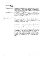
This parameter is a feedback signal to the PI-Controller, displayed in percent.
Press [Up Arrow] to move to the next parameter.
24 LAG MOTRS
RUNNING
Number of lag motors running in Pump and Fan control.
25 CONTROLLER
OUTPUT
Output value of the PI-Controller. Value is in percent of the regulation range.
ACT VALUE 1 (PFC)
Unscaled actual feedback signal number one. Displayed in the units set by
Parameter 40.2.30 (Display Unit).
ACT VALUE 2 (PFC)
Unscaled actual feedback signal number two. Displayed in the units set by
Parameter 40.2.31 (Displ Unit Scale).
Motor Control Values
During motor operation, or when troubleshooting, you may need to check the
vital statistics of the motor and drive. Operating Data Parameters 1 – 8 allow
you to view motor and drive activity.
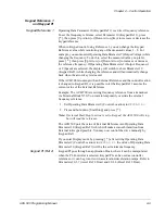
When controlling the drive from the keypad, you may adjust motor speed
while displaying Operating Data Parameters 1 – 8. To do this while viewing
these parameters:
1. Press [ * ] to enter the Setting mode.
2. Press [Up Arrow] to increase motor speed or [Down Arrow] to decrease
motor speed.
When viewing Operating Data Parameters 1 (Output Frequency) and 2
(Speed), the LCD display changes to show Operating Data Parameter 10
(Keypad Ref 1) while pressing the [Up Arrow] or [Down Arrow].


