


Chapter 6 – Parameters
6-10
ACH 500 Programming Manual
Group 10.5
Analog Inputs
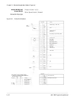
These parameter values can be altered with the ACH 500 running. The Range/
Unit column in Table 6-7 shows parameter values. The text following the
table explains parameter values in detail.
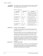
Table 6-7
Group 10.5
1 MINIMUM AI1
0V/0mA; 2V/4mA; READ INPUT
This parameter sets the minimum value of the signal to be applied to AI1.
This value will then correspond to zero speed. Typical minimum values are
0 V/0 mA or 2 V/4 mA.
When input minimum is not 0 or 2 V for a voltage signal, or 0 or 4 mA for a
current signal, the drive can read the minimum from this third display by
applying the minimum signal to the analog input, and pressing [ * ]. This
value then becomes the minimum. The range is 0 – 10 V, and 0 – 20 mA.
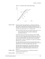
The ACH 500 has a “living zero” function which allows the protection and
supervision circuits to detect a loss of signal. For this feature to be functional,
the minimum input signal must be greater than 0.3 V/0.6 mA. When the
minimum is set less than this level, the “/” between the volts and milliamps
will disappear, indicating the “living zero” is not active even if it has been
programmed.
2 MAXIMUM AI1
10V/20mA; READ INPUT
When the maximum reference is less than 10 V or 20 mA, this parameter will
set what the maximum reference is, so the drive will run at full speed when
this reference is applied. By going into this parameter and applying the
maximum reference, pressing [ * ] will store the applied reference, and the
ACH 500 will consider this value to be maximum.
Parameter
Range/Unit
Description
1 MINIMUM AI1
V/mA
Minimum value of AI1. Value to
correspond to minimum reference.
2 MAXIMUM AI1
V/mA
Maximum value of AI1. Value to
correspond to maximum reference.
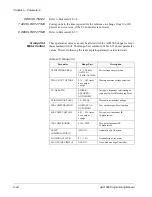
3 RC FILTER ON AI1
0.01 – 10s
Filter time constant for AI1.
4 INVERT AI1
No/Yes
Analog Input signal 1 inversion.
5 MINIMUM AI2
V/mA
Minimum value of AI2. Value to
correspond to minimum reference.
6 MAXIMUM AI2
V/mA
Maximum value of AI2. Value to
correspond to maximum reference.
7 RC FILTER ON AI2
0.01 – 10s
Filter time constant for AI2.
8 INVERT AI2
No/Yes
Analog Input signal 2 inversion.


