


Chapter 6 – Parameters
6-20
ACH 500 Programming Manual
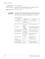
Group 20.3
Accel/Decel
These parameter values can be altered with the ACH 500 running, except
those marked with (O). The Range/Unit column in Table 6-12 shows
parameter values. The text following the table explains parameter values in
detail.
Table 6-12 Group 20.3
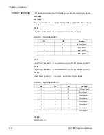
1 ACC/DEC 1OR2 SEL
This parameter defines which Digital Input (1 – 6) is used to select the
Acceleration/Deceleration Ramp used. 0 V DC equals Acc/Dec Time 1, 24 V
DC equals Acc/Dec Time 2.
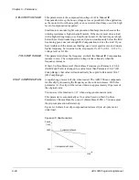
2 ACC/DEC
RAMP SHAPE
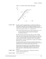
This parameter allows you to select the shape of the acceleration/deceleration
ramp. The available options are:
LINEAR
Suitable for drives requiring steady acceleration/deceleration and/or slow
ramps.
S1 SHAPE
Suitable for ramp times less than one second.
S2 SHAPE
Suitable for ramp times less than 1.5 seconds.
S3 SHAPE
Suitable for ramp times up to 15 seconds.
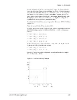
Figure 6-5 shows acceleration and deceleration ramp shapes.
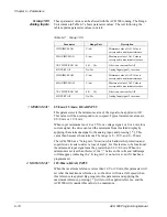
Parameter
Range/Unit
Description
1 ACC/DEC 1OR2 SEL (O)
Not Sel/
DI1–DI6
Acceleration/Deceleration ramp
selection.
2 ACC/DEC RAMP SHAPE
Linear/S1 – S3
Accel./Decel. ramp shape selection.
3 ACCEL TIME 1
0.1 – 1800s
Time for output frequency min. to
max. acceleration ramp 1.
4 DECEL TIME 1
0.1 – 1800s
Time for output frequency max. to
min. deceleration ramp 1.
5 ACCEL TIME 2
0.1 – 1800s
Time for output frequency min. to
max. acceleration ramp 2.
6 DECEL TIME 2
0.1 – 1800s
Time for output frequency max. to
min. deceleration ramp 2.
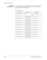
7 ACCEL REF2 TIME
0.1 – 1800s
Ref2 acceleration ramp time for
0 – 100%.
8 DECEL REF2 TIME
0.1 – 1800s
Ref2 deceleration ramp time for
100 – 0%.


