


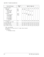


Chapter 6 – Parameters
6-54
ACH 500 Programming Manual
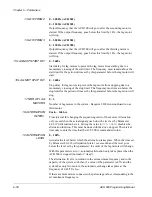
30 DISPLAY UNIT
NO UNIT; bar; %; m/s; °C; °F; diff temp; kPa; 1/min; m
3
/min; gpm; psi;
dpsi; cFm; ft; in.; inHg
Unit of ACT1 and ACT2 indicated on the display.
31 DISPL UNIT SCALE
0 – 50000
Scaling factor for display unit.
32 NBR OF DECIMALS
0 – 5
Number of decimal places in the displayed actual values.
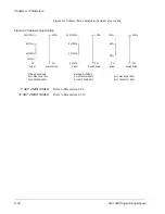
Sample PFC Application
One example of automatic Pump and Fan Control application is fresh water
constant pressure control with two pumps.
In this example a pump station has two pumps used to maintain constant
pressure at different flow situations. One of the pumps is speed regulated with
an ACH 500 and the other is a constant speed pump ON/OFF controlled with
the PFC macro.
Note: The other pump could also be controlled by an ACH 500.
When water consumption is less than the nominal output of the pump, PFC
controls the speed of the regulated pump downwards so that production of the
pump equals the demand. If water consumption increases, the PFC regulator
speed of the pump increases equally until the start limit of the constant speed
pump is reached (start limit = set value of Parameter 40.2.9 (Start Freq 1) + 1
Hz). Start occurs after the set start delay (set value of Parameter 40.2.15) if
demand remains above the start limit for longer than the start delay. When the
constant speed pump starts, the speed of the regulated pump will
automatically regulate to the set low frequency 1 value (Parameter 40.2.12).
If the demand increases further, the speed of the regulated pump regulates
upwards, maintaining equal pressure in the system.
If demand decreases, the speed of the regulated pump first regulates
downwards until the stop limit (stop limit = set value of Parameter 40.2.12
(Low Freq 1) - 1 Hz) of the constant speed pump is reached. The constant
speed pump is stopped after the set stop delay (Parameter 40.2.16) if demand
remains below the stop limit for longer than the stop delay. When the constant
speed pump stops, the speed of the regulated pump will increase to meet the
demand. Refer to Figure 6-22 for an example of pump automation.
If a start limit of an auxiliary pump has been set higher than the maximum
frequency of the ACH 500, the lag pump starts at the defined start limit
because the output of the PI regulator has not been limited by the maximum
frequency of the ACH 500.
If a stop limit is set lower than the minimum frequency of the ACH 500, a lag
pump will stop at the defined stop limit because the output of the PI regulator
has not been limited by the minimum frequency of the ACH 500.
As long as the output of the regulator remains above the maximum frequency
or below the minimum frequency, the regulated pump runs at the
corresponding frequency limit.


