32 OI/266/HART-EN Rev. D
| 2600T Series Pressure transmitters
266 Models - HART
Commissioning
Once the transmitter has been installed, it is put into operation by switching on the operating voltage.
Check the following before switching on the operating voltage:
– Process connections
– Electrical connection
– The impulse line/s and the measuring chamber of the measuring equipment must be completely filled with the measuring
medium.
The transmitter can then be put into operation. To do this, the shut-off valves must be actuated in the following sequence (in the
default setting, all valves are closed).
(Differential models) 266Dx or 266Mx
– Open the shut-off valves on the pressure tap connection (if present).
– Open the pressure equalization valve of the manifold.
– Open the positive shut-off valve (on the manifold)
– Open the negative shut-off valve (on the manifold)
– Close the pressure equalization valve.
To put the transmitter out of operation, carry out the steps in reverse order.
(Gauge & Absolute models) 266Gx, 266Ax, 266Hx, 266Nx, 266Px, 266Vx, 266Rx
– Open the shut-off valve on the pressure tap connection (if present).
– Open the positive shut-off valve.
To put the transmitter out of operation, carry out the steps in reverse order.
Important
For the absolute pressure transmitters model 266AS, 266NS, 266RS or 266VS with sensor range C, F or G, please be aware that the measuring equipment
will have been overloaded by the atmospheric pressure due to the long periods of transport and storage involved.
For this reason, you will need to allow a starting time of approx. 30 minutes for 266Vx, 266Rx and 266Nx models and approx. 3 hours for 266Ax models
after commissioning, until the sensor has stabilized to such an extent that the specified accuracy can be maintained.
If, when using “intrinsically safe” transmitters, an ammeter is connected to the output circuit or a modem is connected in parallel while there is a risk of
explosion, the sums of the capacitances and inductances of all circuits, including the transmitter (see EC-type-examination certificate) must be equal to or
less than the permissible capacitances and inductances of the intrinsically safe signal circuit (see EC-type-examination certificate for the supply unit).
Only passive or explosion-proof devices or indicators may be connected.
If the output signal stabilizes only slowly, it is likely that a large damping time constant has been set on the transmitter.
Analogue and HART Communication models
If the pressure applied falls within the values indicated on the name plate, the output current will be between 4 and 20 mA.
If the pressure applied falls outside the set range, the output current will be between 3.5 mA and 4 mA if the range is undershot
or between 20 mA and 22.5 mA if the range is overshot (depending on the respective configuration).
Standard setting for normal operation
3.8 mA / 20.5 mA
In order to prevent errors in flow rate measurements (266Dx and 266Mx) in the lower range, it is possible to set a “cut off point”
and/or a “lin./sq. root transition point” via the optional LCD integral displays or via the graphical user interface (DTM).
Unless otherwise specified, the “lin./sq. root transition point” is set to 5% and the “cutoff” to 6% of the flow rate end value by the
manufacturer; A current that is < 4 mA or > 20 mA may also indicate that the microprocessor has detected an internal error. In this
case the alarm output can be configured both via the local LCD or via an external Hart hand held terminal (ABB 691HT, DHH801
etc) or via a DTM based configuration tool (Asset Vision).
Standard setting for error detection (alarm)
21 mA
The graphical user interface (DTM) or the LCD integral display
(if installed) can be used to diagnose the error.
Important
A brief interruption in the power supply results in initialization of the
electronics (program restarts).
Summary of Contents for 266 HART Series
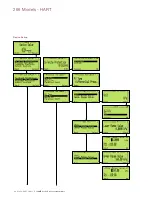
Page 40: ...40 OI 266 HART EN Rev D 2600T Series Pressure transmitters 266 Models HART Device Set up ...
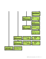
Page 41: ...2600T Series Pressure transmitters OI 266 HART EN Rev D 41 ...
Page 42: ...42 OI 266 HART EN Rev D 2600T Series Pressure transmitters 266 Models HART ...
Page 43: ...2600T Series Pressure transmitters OI 266 HART EN Rev D 43 ...
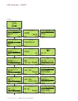
Page 44: ...44 OI 266 HART EN Rev D 2600T Series Pressure transmitters 266 Models HART Display ...
Page 45: ...2600T Series Pressure transmitters OI 266 HART EN Rev D 45 ...
Page 46: ...46 OI 266 HART EN Rev D 2600T Series Pressure transmitters 266 Models HART ...
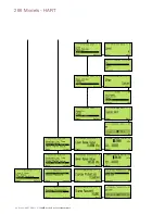
Page 48: ...48 OI 266 HART EN Rev D 2600T Series Pressure transmitters 266 Models HART Calibrate ...
Page 49: ...2600T Series Pressure transmitters OI 266 HART EN Rev D 49 Totalizer ...
Page 50: ...50 OI 266 HART EN Rev D 2600T Series Pressure transmitters 266 Models HART ...
Page 51: ...2600T Series Pressure transmitters OI 266 HART EN Rev D 51 ...
Page 52: ...52 OI 266 HART EN Rev D 2600T Series Pressure transmitters 266 Models HART Diagnostics ...
Page 53: ...2600T Series Pressure transmitters OI 266 HART EN Rev D 53 Device Info ...
Page 54: ...54 OI 266 HART EN Rev D 2600T Series Pressure transmitters 266 Models HART Communication ...
Page 77: ...2600T Series Pressure transmitters OI 266 HART EN Rev D 77 ...
Page 78: ...78 OI 266 HART EN Rev D 2600T Series Pressure transmitters 266 Models HART ...
Page 79: ...2600T Series Pressure transmitters OI 266 HART EN Rev D 79 ...

