2600T Series Pressure transmitters |
OI/266/HART-EN Rev. D 35
Factory settings
Transmitters are calibrated at the factory to the customer’s specified measuring range. The calibrated range is provided on the
name plate whereas the tag number on the additional tag plate.
The calibrated range and tag number are provided on the name plate. If this data has not been specified, the transmitter will be
delivered with the following configuration:
Parameter
Factory setting
Lower Range Value (LRV) (4 mA)
Zero
Upper Range Value (URV) (20 mA)
Upper Range Limit (URL)
Output transfer function
Linear
Damping
1 second
Transmitter failure (alarm)
Upscale (21.8 mA)
Optional LCD HMI scale
1 line PV and output signal bargraph
Important
Every of the configurable parameters here on the left can easily be
modified either via the optional LCD HMI, with an HART handheld
terminal or a compatible software solution. Information regarding
flange type and material, O-ring materials, and filling liquid type is
stored inside the non-volatile memory of the device.
Configuration types
Pressure transmitters can be configured as follows:
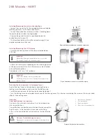
– Configuration of the parameters for the lower and upper range values (via Zero and Span pushbuttons), without an integral LCD HMI.
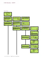
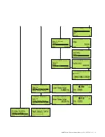
– Configuration of the pressure transmitter using the integral LCD HMI (menu-controlled)
– Configuration with a handheld terminal
– Configuration using a PC/laptop via the graphical user interface (DTM)
Configuring the transmitter without an integral LCD HMI
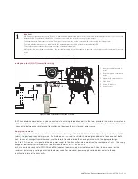
The “lower range value” and “span” parameters can be set directly on the transmitter using the External pushbuttons.
The transmitter has been calibrated by the manufacturer based on the order information. The tag plate contains information on the
“lower range value” and “upper range value” set. In general, the following applies:
The first pressure value (e.g., 0 mbar) is always assigned to the 4 mA signal (or 0%), while the second pressure value (e.g., 400
mbar) is always assigned to the 20 mA signal (or 100%). To change the transmitter ranging apply the pressure for the “lower range
value” and “upper range value” to the measuring equipment. Make sure that the measuring limits are not exceeded.
Important
Reducing station with adjustable pressure and reference displays can
be used as pressure generators.
When making the connection, please ensure that there are no resid-
ual fluids (for gaseous testing materials) or air bubbles (for fluid
testing materials) in the impulse lines, since these can lead to errors
during inspection. Any potential measuring error for the pressure gen-
erator should be at least three times smaller than the desired
measuring error for the transmitter. It is recommended that the
damping is set to 1 second.
Important
In case of the 266 transmitter for absolute pressure (266Vx, 266Rx,
266Ax and 266Nx) with a measuring range less than or equal 650
mbar abs., please be aware that the measuring equipment will have
been overloaded by the atmospheric pressure due to the long
periods of transport and storage involved. For this reason, you will
need to allow a starting time of approx. 30 minutes for 266Vx,
266Rx and 266Nx models and 3 hours for 266Ax models after
commissioning, until the sensor has stabilized to such an extent
that the specified accuracy can be maintained.
LRV and URV configuration (4 ... 20 mA ranging)
– Apply the pressure for the “lower range value” and wait approx. 30 s until it has stabilized.
– Press the “Z” button. This sets the output current to 4 mA.
– Apply the pressure for the “upper range value” and wait approx. 30 s until it has stabilized.
– Press the “S” button. This sets the output current to 20 mA.
– If required, reset the damping to its original value.
– Record the new settings. The respective parameter will be stored in the non-volatile memory 10 seconds after the “Z” or “S”
button is last pressed.
Summary of Contents for 266 HART Series
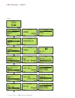
Page 40: ...40 OI 266 HART EN Rev D 2600T Series Pressure transmitters 266 Models HART Device Set up ...
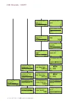
Page 41: ...2600T Series Pressure transmitters OI 266 HART EN Rev D 41 ...
Page 42: ...42 OI 266 HART EN Rev D 2600T Series Pressure transmitters 266 Models HART ...
Page 43: ...2600T Series Pressure transmitters OI 266 HART EN Rev D 43 ...
Page 44: ...44 OI 266 HART EN Rev D 2600T Series Pressure transmitters 266 Models HART Display ...
Page 45: ...2600T Series Pressure transmitters OI 266 HART EN Rev D 45 ...
Page 46: ...46 OI 266 HART EN Rev D 2600T Series Pressure transmitters 266 Models HART ...
Page 48: ...48 OI 266 HART EN Rev D 2600T Series Pressure transmitters 266 Models HART Calibrate ...
Page 49: ...2600T Series Pressure transmitters OI 266 HART EN Rev D 49 Totalizer ...
Page 50: ...50 OI 266 HART EN Rev D 2600T Series Pressure transmitters 266 Models HART ...
Page 51: ...2600T Series Pressure transmitters OI 266 HART EN Rev D 51 ...
Page 52: ...52 OI 266 HART EN Rev D 2600T Series Pressure transmitters 266 Models HART Diagnostics ...
Page 53: ...2600T Series Pressure transmitters OI 266 HART EN Rev D 53 Device Info ...
Page 54: ...54 OI 266 HART EN Rev D 2600T Series Pressure transmitters 266 Models HART Communication ...
Page 77: ...2600T Series Pressure transmitters OI 266 HART EN Rev D 77 ...
Page 78: ...78 OI 266 HART EN Rev D 2600T Series Pressure transmitters 266 Models HART ...
Page 79: ...2600T Series Pressure transmitters OI 266 HART EN Rev D 79 ...

