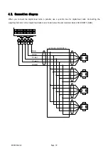
AD4329A-DLC
Page 11
4.3. When connecting more than 6 load cells
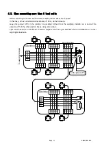
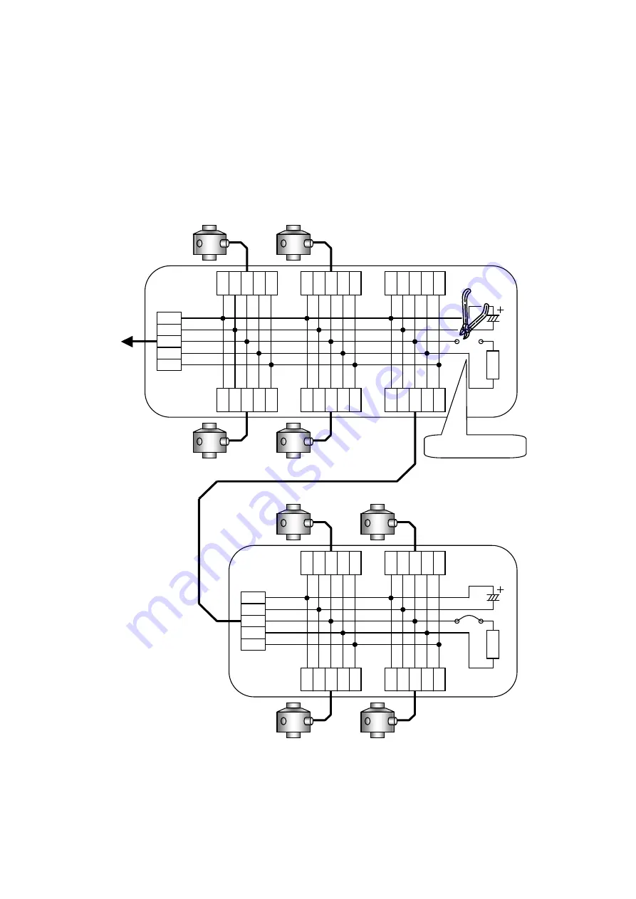
When connecting more than six load cells, multiple junction boxes are required.
In that case, to have a termination resistance of 100
, do the following.
Leave the jumper (JP1) in the junction box installed furthest from the weighing indicator as is and cut the
jumpers (JP1) in the other junction boxes, using wire cutters.
Fig.4 shown below is an example connection diagram when using an AD4388-4 and an AD4388-6 to connect
eight digital load cells
.
R W G B Y
100
C1
R1
JP1
100
C1
R1
JP1
R
W
G
B
Y
To
weighi
ng indicator
No connection
Cut the jumper (JP1).
AD4388-6
AD4388-4
R W G B Y
R W G B Y
R W G B Y
R W G B Y
R W G B Y
R W G B Y
R W G B Y
R
W
G
B
Y
R W G B Y
R W G B Y


