Operating and Assembly Instructions Flexilo FLAT BOTTOM for wood pellets
Assembly
Subject to technical change
Issue 09/2016
Page 17 of 32
©A.B.S. Silo- und Förderanlagen GmbH
5 Assembly
5.1
Pre-Assembly of the drawing irons
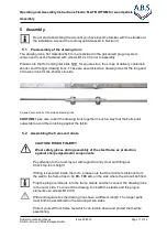
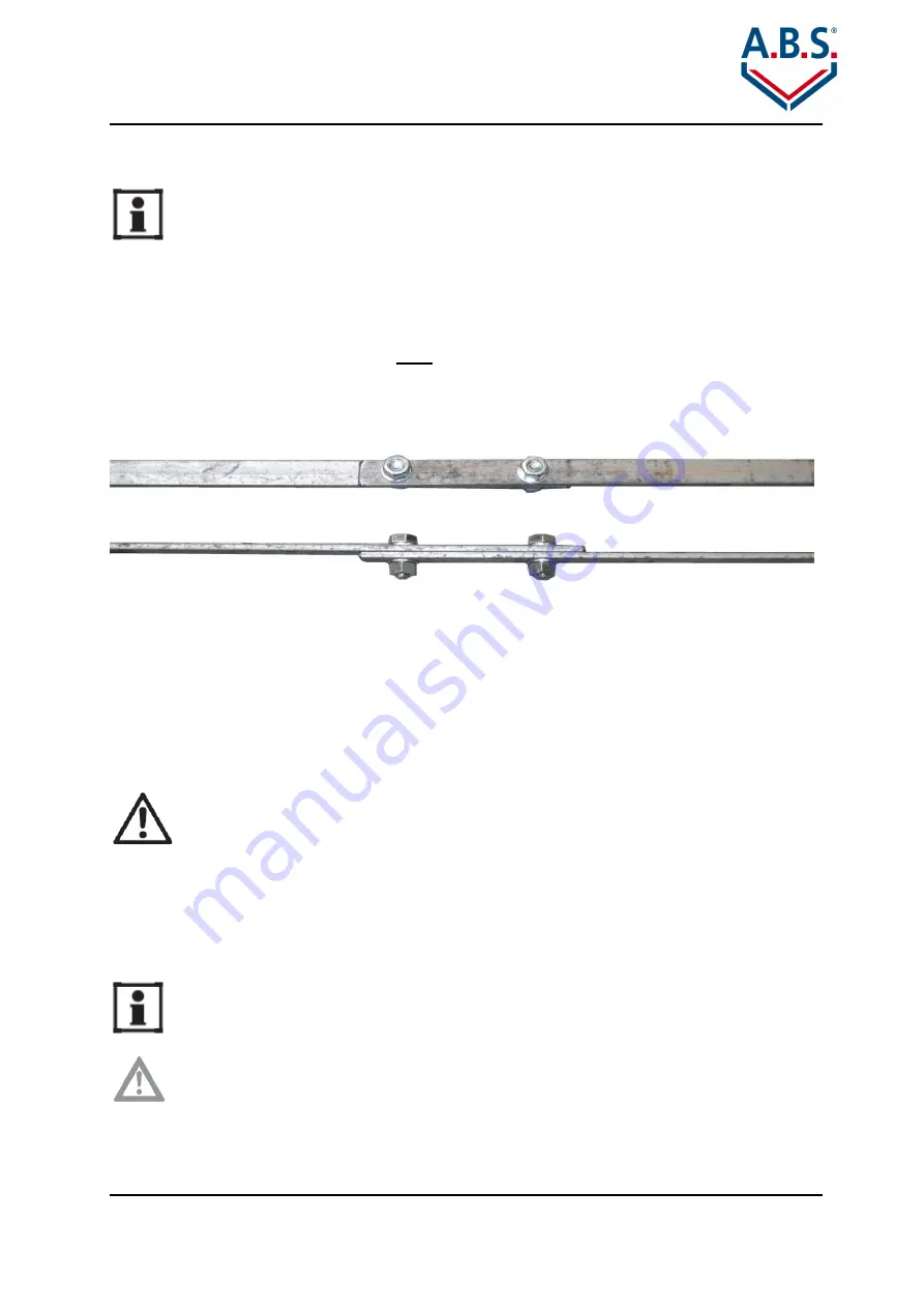
The drawing irons, flat material 25x5 mm, are divided in the galvanized plug-in system
version and must be fastened with screws M12 x 30 prior to assembly .
Please note that for rectangular silos, NOT for square silos, the scope of delivery contains 8
shorter and 8 longer drawing irons. These are assembled to 4 drawing irons for the long and
4 drawing irons for the shorter silo side.
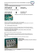
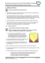
Screwed connection of the divided drawing irons
CAUTION: Take care to bolt the drawing irons together in such a way that the bolts point
outwards to avoid them rubbing against the fabric.
5.2
Assembling the frame and struts
Do not start assembling the silo until you have become familiar with the situation at
the installation site and the room layout discussed in Section 3.
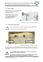
CAUTION! RISK OF INJURY!
Wear safety gloves during assembly of the steel frame as protection
against sharp edged metal components.
Pay attention to the room layout with regard to entry door and filling set.
Check the room height.
If filling is executed inside the room, please note that the minimum distance from
the wall to the frame has to be 80 - 100 cm, on the side where the silo will be filled.
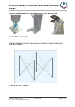
Plug the plug-in elements into the frame stands and then connect the drawing irons
to the outer side. To connect the drawing irons with the stands and the plug-in
elements use screws M12x30.
With rectangular silos the drawing irons have a different length. The longer parts
must both be assembled on the two longer silo sides.
Protect yourself from frame feet which can tumble down and protect them while
assembling.

