Kiosk ePassport Reader User Guide
DT-01822A
© 3M 2007 All rights reserved.
6
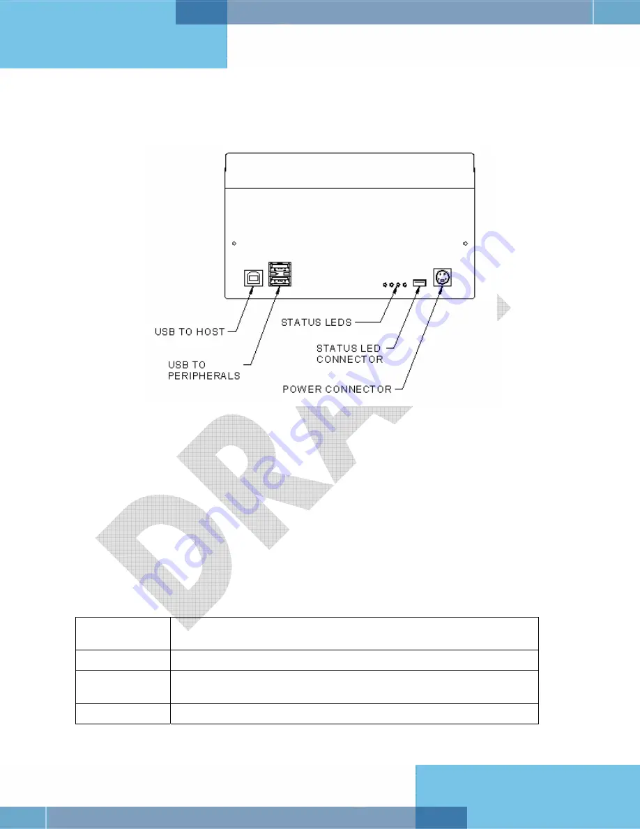
Back Panel
The back panel features the USB communication ports, status LED’s, a connector to drive a
secondary set of status LED’s and a power supply connector.
Figure 4: Back Panel Ports
USB Ports
Communication to and from the host PC is via USB 2.0. The USB host interface is a standard
Type B connector. The reader does not draw any power from the host.
A built-in USB hub and two auxilliary USB 2.0 Type A connectors allow you to connect
additional USB peripherals such as a mouse, keyboard, etc. The two USB peripheral connectors
are capable of sup5V DC at a total of 500mA to the peripherals (e.g. 500mA to a single
peripheral, 250mA to each of two peripherals, etc.).
Status Indicator LED’s
The status LEDs are intended to assist a technician to install and debug the reader, and indicate
the reader status and the result of scanning a document. They are not visible by a user.
Table 1: Indicator LEDs
Ready (Green)
The reader is ready to scan a document (when connected to the host
application).
Busy (Amber)
The reader is scanning a document and processing the data.
OK (Green)
A known document type was presented and processing was
successful.
Error (Red)
The document is of an unknown type or did not process properly.
Summary of Contents for Kiosk ePassport Reader PV35-02 Series
Page 8: ......


