background image

DT-01822A 


Kiosk ePassport Reader User Guide 

© 3M 2007   All rights reserved. 

25

Windows® 2000 

1.


In Windows® 2000, right-click 

My Computer

 and select 

Properties

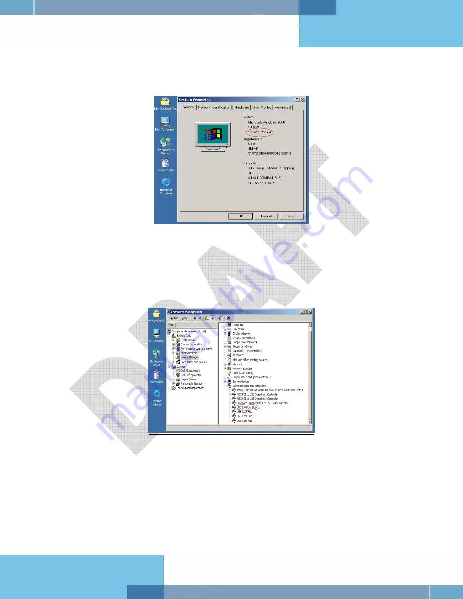
Figure 22: System Properties window 


2.


Locate the version number on the 

General

 tab and verify that 

Service Pack 4

 or greater 

has been installed. 

3.


Right-click 

My Computer

 and select 

Manage

4.


Click on 

Device Manager

 in the 

Tree

 list. 

5.


Under Universal

 Serial Bus controllers

 locate 

USB 2.0 Root Hub

Figure 23: Windows® 2000 SP4 Computer Management window 


6.


If your 

Device


Manager

 displays 

USB 2.0 Root Hub

, the system has high speed USB 

2.0 capability. 

Windows® XP 

1.


In Windows® XP, right-click 

My Computer

 and select 

Manage

. Click on 

Device 

Manager

 in the 

Tree

 list. 

2.


Under 

Universal Serial Bus controllers

 locate an “Enhanced” entry. 

Summary of Contents for Kiosk ePassport Reader PV35-02 Series

Page 1: ...3M e Passport Kiosk Reader User Guide Document Type User Guide Date 29 11 2007 Revision DT 1822A_DRAFT Submitted by 3M Canada Company Security Systems Division ...

Page 2: ...remedy at 3M s option shall be to either repair or replace the Defective Product or refund the purchase price of the Defective Product LIMITATION OF LIABILITY 3M AND SELLER IF ANY SHALL NOT BE LIABLE FOR ANY INJURY LOSS OR DAMAGE WHETHER DIRECT INDIRECT SPECIAL INCIDENTAL OR CONSEQUENTIAL HOWSOEVER CAUSED INCLUDING DAMAGES FOR LOSS OF PROFITS BUSINESS INTERRUPTION LOSS OF BUSINESS INFORMATION INCR...

Page 3: ...ncy Rules and Regulations NOTE This equipment has been tested and found to comply with the limits for a Class A digital device pursuant to Part 15 of the FCC Rules These limits are designed to provide a reasonable protection against harmful interference when the equipment is operated in a commercial environment This equipment generates uses and can radiate radio frequency energy and if not install...

Page 4: ...Canadian IECS 003 Cet appareil numérique de la classe A est conforme à la norme NMB 003 du Canada IC 458A SSDPV35 EMC Compliance Europe This equipment complies with the requirements of the Radio Telecommunications Terminal Equipment RTTE and Electromagnetic Compatibility EMC directives Safety Label Locations Note Depending on the reader model some labels may not be present ...

Page 5: ...dware 9 Unpacking the Reader 9 Kiosk Design Considerations 9 Connecting the Power Supply 12 Connecting to the Host System 12 Installing the Software 13 Host PC Requirements 13 Verifying the USB Driver Installation 16 Updating the USB Drivers 17 Power up Self Test 17 Testing Reading and Communication 18 Maintenance 20 Cleaning 20 Appendix A Specifications 21 Appendix B Troubleshooting 23 Appendix C...

Page 6: ...ded 11 Figure 11 Mounting Not Recommended 11 Figure 12 InstallShield Wizard window 14 Figure 13 License Agreement window 14 Figure 14 Destination Folder window 15 Figure 15 Installation Progress window 15 Figure 16 InstallShield Wizard Complete window 16 Figure 17 System Properties window 16 Figure 18 Device Manager window 17 Figure 19 Successful Test Card Reading 19 Figure 20 Successful RFID Chip...

Page 7: ... ePassport Reader User Guide 3M 2007 All rights reserved vii Table 4 Environmental Specifications 21 Table 5 Communication Interfaces and Protocols 21 Table 6 Regulatory Information 22 Table 7 Troubleshooting Cases 23 ...

Page 8: ......

Page 9: ...y physically installed within a self service kiosk that provides a mechanical housing and limits user access to placing travel documents on the reader s glass imaging surface They have not been evaluated for other uses such as stand alone desktop use or other environmental conditions Explanation of Product Safety Label Symbols Warning Indoor Dry Location Use Only Attention Refer to Instructions Di...

Page 10: ...e Do not use AC power supply and or power cord if damaged Product is to be serviced by 3M service personnel only No user serviceable parts or adjustments inside Do not modify or attempt to modify the reader and or AC power supply Use only in an indoor dry location Do not use the product in an outdoor and or wet environment CAUTION To reduce the risk associated with environmental contamination from...

Page 11: ...rporate the readers into a kiosk as well as guidance on the operation troubleshooting and maintenance of the readers Features Overview The 3M Kiosk Full Page Reader and 3M Kiosk ePassport Reader are a family of intelligent optical character recognition OCR and full image capture devices that provide automated data capture from a variety of personal identification documents They read data from docu...

Page 12: ... or any other page the reader s antenna will detect and read the chip The user does not need to turn the book around to ensure the chip is read The RF radio frequency technology used in the 3M Kiosk ePassport Reader is very short range and does not interfere with other electronic equipment such as PC monitors wireless communications for example 802 11g or cell phones Document Images The following ...

Page 13: ...o a kiosk chassis Document Tray and Window The document window is a glass surface measuring 132mm x 88mm located on top of the reader Users place documents on the document tray imaging side down and slide them to the back of the document window to scan them Guides on the document tray help align the document and keep it pressed onto the glass window The document window is slightly larger than ICAO...

Page 14: ...uch as a mouse keyboard etc The two USB peripheral connectors are capable of supplying 5V DC at a total of 500mA to the peripherals e g 500mA to a single peripheral 250mA to each of two peripherals etc Status Indicator LED s The status LEDs are intended to assist a technician to install and debug the reader and indicate the reader status and the result of scanning a document They are not visible b...

Page 15: ... Figure 5 Status LED Connector Power Connector The reader must be connected to a UL Listed DC power supply capable of providing 12V DC at 1 1A The connector pinouts are shown in the following figure Figure 6 Power Supply Connector Mounting Points The readers contain eight M4 threaded mounting bosses two on each side and four on the bottom as shown in the following figure The preferred mounting poi...

Page 16: ...Kiosk ePassport Reader User Guide DT 01822A 3M 2007 All rights reserved 8 Figure 7 Mounting Mechanical Detail ...

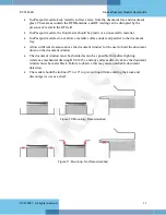
Page 17: ...mounted behind the kiosk front panel with only the document tray protruding The front panel must provide an opening to allow users to insert their documents and hold them flat on the document glass for scanning The opening should form a box open at the front and closed at the top sides and back To better illustrate this a typical kiosk concept is shown in the following figures It is recommended th...

Page 18: ...utaway View The reader is designed to be held in place using four M4 machine screws See the previous section for detailed mechanical dimensions of the reader and its threaded mounting points When designing a kiosk to accommodate the reader consider the following factors Attach the reader using the bottom attachment points if possible ...

Page 19: ...lic surface under and parallel to the document tray Allow sufficient clearance above the document window for the user to hold the document down on the document window The document window must be shielded as much as possible from direct lighting reference mechanical drawing DT 01823 and any surfaces directly above the document window must be matte black Failure to observe this may cause unreliable ...

Page 20: ...upply to the power connector at the rear of the reader and secure or tie off the cable as required A suitable power supply p n CA000006747 may be purchased from 3M if required Contact your Sales representative or 3M Global Technical Services GTS for details Connecting to the Host System The reader is supplied with a 2 meter USB A B communication cable 1 Insert the USB connector of the supplied cab...

Page 21: ...pt to install the application without the required operating system and service packs prior to installation You must have PC Administrative rights to install the software Installing the Software The installation CD installs 3M Authentication Software and SDK Imaging Device Driver Smart Card Reader Driver ePassport option only Contactless Reader Driver ePassport option only Additional SDKs based on...

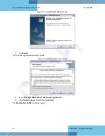
Page 22: ...eserved 14 Figure 12 InstallShield Wizard window 2 Click Next The License Agreement window opens Figure 13 License Agreement window 3 Select I accept the terms of the license agreement 4 Click Next to proceed with the installation The Destination Folder window opens ...

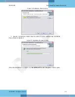
Page 23: ...ed 15 Figure 14 Destination Folder window 5 Specify a destination folder where the software will be installed and click Next The software is installed Figure 15 Installation Progress window When the installation is complete the InstallShield Wizard Complete window opens ...

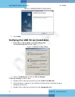
Page 24: ...click on Properties The System Properties window opens Figure 17 System Properties window 2 Click on the Hardware tab then on Device Manager The Device Manager window opens 3 Expand click on the plus sign the entry called Smart Card Readers 4 Verify that there are entries for the USB SmartCard and USB Contactless Readers ePassport option only 5 Expand click on the plus sign the entry called Imagin...

Page 25: ...o update the driver 1 In the Device Manager double click the invalid device that looks like the reader 2 Select the Driver tab and click Update driver 3 Follow the instructions above for performing the driver installation Power up Self Test A power up self test occurs automatically when the reader powers up If the reader is installed correctly and is operational the status LEDs perform the followi...

Page 26: ...g OCR data as well as a programmed contactless chip Readers without the ePassport option are supplied with test card DS 00034 containing only OCR data 4 Place the test card face down on the document tray aligned with the left guide 5 Push the card to the back of the document window until it stops Note Do not move the document during the scanning process 6 Observe the LEDs during the scanning proce...

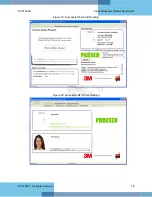
Page 27: ...DT 01822A Kiosk ePassport Reader User Guide 3M 2007 All rights reserved 19 Figure 19 Successful Test Card Reading Figure 20 Successful RFID Chip Reading ...

Page 28: ...s the Scotch Brite Microfiber Cleaning Cloth provided To reorder cleaning cloths p n G 00037 contact Global Technical Services GTS See Appendix D Customer Service on page 26 for more information 1 Clean the document window with a clean cloth For stubborn dirt use a mild glass cleaner or a lightly dampened cloth water Note Do not use abrasive cleaners or solvents These may scratch the glass or dama...

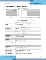
Page 29: ...umption 3 watts not including USB peripherals Connector 4 pin Mini DIN Table 4 Environmental Specifications Temperature Operating 0 40 C 32 104 F Storage 20 50 C 4 122 F Humidity Operating 20 80 non condensing Storage 5 95 non condensing Table 5 Communication Interfaces and Protocols Connection Interface USB 2 0 480 Mbit s High Speed Host USB Power Reader draws no power from host USB connector USB...

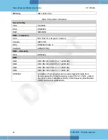
Page 30: ...EEA EN55022 Class A Australia AS NZS 3548 EMC immunity EEA EN55024 EMC EMC ESTI EN 301 489 1 V1 2 1 2000 08 EMC ESTI EN 301 489 3 V1 2 1 2000 08 EMC ESTI EN 300 330 1 V1 3 1 2001 06 EMC ESTI EN 300 330 2 V1 1 1 2001 06 EN50364 Limitation of human exposure to electromagnetic fields from devices operating in the frequency range 0 Hz to 10 GHz used in electronic article surveillance EAS radio frequen...

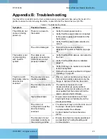
Page 31: ... host Verify that the USB driver is installed page 16 Verify that only one reader is connected to the host system Follow the procedure outlined in Chipset Updating on page 26 The document is non machine readable This is a normal condition when there is no machine readable data and only the image is captured from the document The document is poorly printed The reader is designed to read documents t...

Page 32: ...strative rights to install the software Consult with your IT support representative LEDs do not change after reading an RF chip Normal This is a normal condition RF status is displayed only on the host screen Reader becomes unresponsive Depending on the implementation of the PC application and the volume of USB traffic AC line transients may cause unrecoverable errors in USB data transmissions Res...

Page 33: ...installed 3 Right click My Computer and select Manage 4 Click on Device Manager in the Tree list 5 Under Universal Serial Bus controllers locate USB 2 0 Root Hub Figure 23 Windows 2000 SP4 Computer Management window 6 If your Device Manager displays USB 2 0 Root Hub the system has high speed USB 2 0 capability Windows XP 1 In Windows XP right click My Computer and select Manage Click on Device Man...

Page 34: ... High Speed USB 2 0 process determines if the PC has the correct hardware Chipset updating ensures that the PC also has the correct driver software for that hardware The program chipid exe is used to determine your chipset It is available in the install directory on your system following installation If the workstation uses the Intel USB chipset follow this link to locate the latest updates http d...

Page 35: ...UK 44 0 1344 858000 fax 44 0 1344 858792 email 3M AiT gcs mmm com Return to Depot Maintenance Procedure In the event of a suspected problem with 3M equipment Diagnose The end user system manager will ascertain that there is an actual fault with the equipment that cannot be rectified with the use of the applicable User Guide or local in house knowledge Initiate Call The end user system manager shou...

Page 36: ...e damage during transit The CUSTOMER is responsible for insurance coverage on the reader during transit to 3M in case of loss or damage The reader should then be returned to the 3M designated service depot Repair When the defective equipment is received at the service depot the reader will be repaired tested and returned to THE CUSTOMER s central depot Subject to unavoidable delays this effort sho...

Reviews: